Rough yarn-series suspended spindle capable of automatically keeping yarn leading tension constant

A hanging spindle and automatic technology, which is applied in the field of cotton spinning, can solve the problems of increasing the operator's operating strength, the yarn sliver is easy to fall, and has a hard end, and achieves the effects of easy promotion, less cost increase and simple structure.

Active Publication Date: 2012-05-02
江阴市通隆纺织机械有限公司
View PDF8 Cites 3 Cited by
  • Summary
  • Abstract
  • Description
  • Claims
  • Application Information

AI Technical Summary

Problems solved by technology

When the roving tube is full of roving, the hanging spindle bears the greatest gravity and frictional force. When the coarse sand is pulled, it is prone to accidental elongation and hard ends, which increases the operating strength of the operator and affects the spinning quality; When the roving wound on the roving bobbin decreases gradually, the frictional force also decreases. Under the same traction force, the sliver is easy to fall, and the roving bobbin stops rotating at this time

Method used


Image

  • Rough yarn-series suspended spindle capable of automatically keeping yarn leading tension constant
  • Rough yarn-series suspended spindle capable of automatically keeping yarn leading tension constant

Examples


Embodiment 1

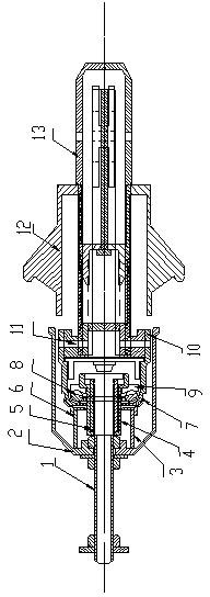
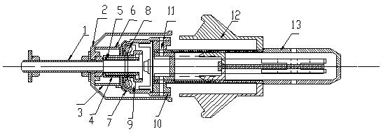
[0023] This embodiment is applicable to the situation of low yarn drawing tension. Hanging spindle screw 1 is fixed with the spinning frame by the nut at the upper end, and the hanging spindle screw is fixed with the hanging spindle cap 2 through the nut in the middle of the screw, and the weight spring jacket 4 is installed at the end of the hanging spindle screw, and the weight is installed between the weight spring jacket and the hanging spindle screw. Spring 5, the steel ball cage 9 is set on the shoulder of the weight spring jacket, a plurality of steel balls 8 are installed on the steel ball cage, the steel ball bowl 7 is set above the steel ball cage, and the steel ball bowl is set above the steel ball bowl to slide with it The contacting damping cover 6 is set with a damping spring 3 between the outside of the top of the damping cover and the inside of the top of the hanging cap, and the inner sleeve 10 of the hanging spindle at the lower end of the steel ball bowl is f...

Embodiment 2

[0028] This embodiment is applicable to the situation of yarn drawing tension wool spinning of all spinning raw materials. On the basis of applying the technical solution of Example 1, the following structure is added: between the top of the damping spring 3 and the hanging spindle cap, the lower card 16 is set and fixed on the hanging spindle screw, and the supporting step adjustment is set on the lower card. The support spring 17 of part 14 is set with a stepping adjustment part 14 at the support spring upper end, and a stepping insertion rod 15 is connected on the stepping adjustment part, and a stepping block 18 is set above the stepping insertion rod, and the stepping block passes through Upper card 19 is fixed with hanging spindle screw rod 1, and the stepping insert rod is inserted in the stepping groove of corresponding spinning raw material on the stepping block, and the set hanging spindle cap 2 is set on the stepping block. During operation, as long as the step adju...


PUM


Abstract

The invention discloses a rough yarn-series suspended spindle capable of automatically keeping yarn leading tension constant, which relates to the field of spinning machine components and is used for solving the problems of accidental micro-section traction and the formation of long snick yarn defects caused by easy falling of silvers when rough yarns approach a hollow tube since the yarn leading tension of the conventional suspended spindle cannot be kept constant and accidental extension and hard head projection are easily caused when a roving bobbin is filled with yarns. In a technology disclosed by the invention, a weight spring and a damping spring are arranged in a suspended spindle cap and used for adjusting the yarn leading tension; in a wide yarn leading tension range, a tension gear shifting device is arranged on the basis of the structure, fixed control force is pre-adjusted, and the spring is used for controlling the rest of the force value. The rough yarn-series suspended spindle has the characteristic of keeping the yarn leading tension of all common raw material-series rough yarns constant, and has the beneficial effects of simple structure, small increase in the cost and convenience for popularization.

Description

technical field [0001] The invention relates to the field of textile machinery, in particular to raw material spinning machine parts for cotton spinning, hemp spinning, silk spinning, wool spinning and chemical fiber spinning. Background technique [0002] In the weaving process, it goes through the roving process and then to the spinning process. The roving spun in the roving process is wound on the roving bobbin, and then the roving bobbin is loaded on the hanging spindle, and then the roving is drawn to the spinning frame for the next step of processing. With the running of the spinning frame, the roving is continuously pulled from the roving bobbin through the spinning frame and twisted. In order to make the traction speed uniform, the technology of 20 years ago has been used on the hanging spindle, that is, in the early 1980s, Jingwei Textile, Shanghai No. 2 Textile and the Equipment Department of the Ministry of Textiles jointly established a plastic textile fitting in...

Claims


Application Information

Patent Timeline
Patent Type & Authority Applications(China)
IPC IPC(8): D01H1/18D01H13/10
Inventor 徐国平王平祖
Owner 江阴市通隆纺织机械有限公司
Why Eureka
Try Eureka