

Manufacture method for rubber mount structure
A manufacturing method and suspension technology, which are applied in the field of auto parts manufacturing, can solve the problems of high mold cost and increase the manufacturing cost of rubber mounts, and achieve the effect of saving labor costs and reducing manufacturing costs.
- Summary
- Abstract
- Description
- Claims
- Application Information
AI Technical Summary
Problems solved by technology
Method used
Image

Examples
Embodiment Construction
[0019] Below with reference to the accompanying drawings, through the description of the embodiments, the specific embodiments of the present invention, such as the shape, structure, mutual position and connection relationship between the various parts, the role and working principle of the various parts, etc., will be further described. Detailed instructions:
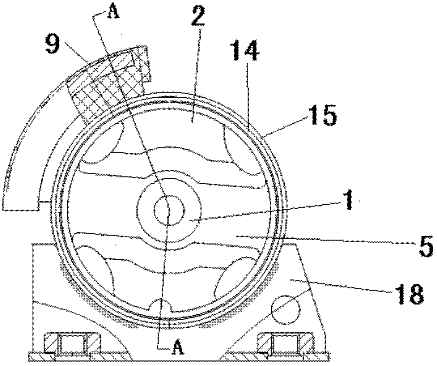
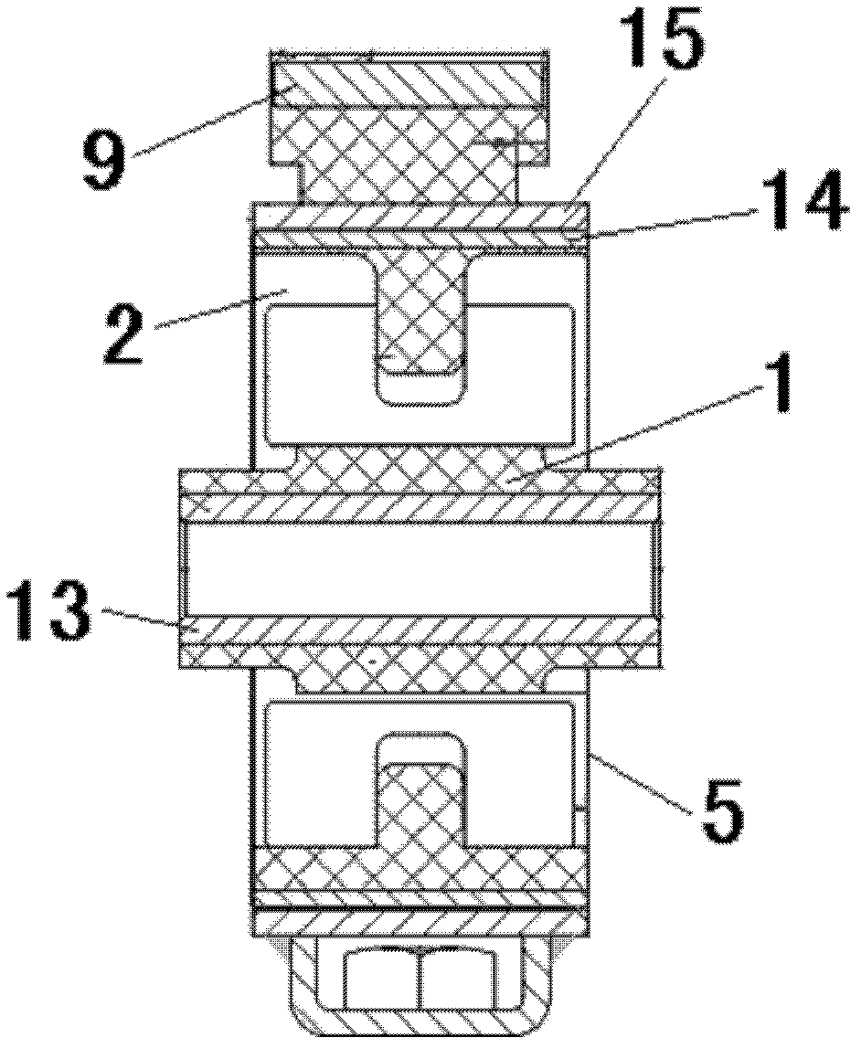
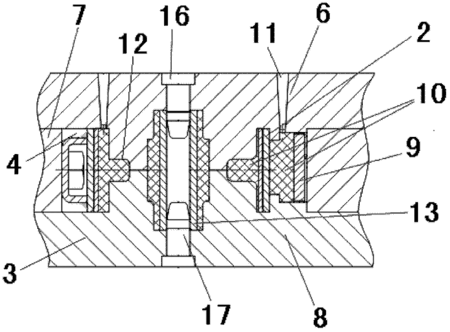
[0020] as attached figure 1 - attached image 3 As shown, the present invention is a manufacturing method of a rubber suspension, which includes a suspension structure body 5. When the rubber suspension is manufactured, the inner tube 14 is first pressed onto the base welding assembly 2, and then the base The welding assembly 2 and the bushing 1 are placed in the mold cavity 4 of the mold 3, and by injecting the colloid 10 into the mold cavity 4, vulcanization is processed into a suspension including the bushing 1, the inner tube 14 and the base welding assembly 2 Structural ontology5.
[0021] The bushing 1 and bas...
PUM
 Abstract
Description
Claims
Application Information