
Low-carbon and environment-friendly feeding system

A low-carbon, environmentally friendly, feeding device technology, applied in fish farming, applications, animal husbandry, etc., can solve the problems of easy damage to mechanical equipment, high cost, and increased fish farming costs, saving packaging costs, small weather effects, Labor saving effect

Inactive Publication Date: 2011-01-12
秦琳玲
View PDF0 Cites 19 Cited by
  • Summary
  • Abstract
  • Description
  • Claims
  • Application Information

AI Technical Summary

Problems solved by technology

[0005] First, it affects the quality of the feed: if it is windy and rainy, the feed may be wet during the process of transporting the feed, which will affect the quality of the feed. At the same time, the automatic bait feeding machine is not completely sealed, and the feed in the bait feeding machine will also be damp. These will lead to an increase in the cost of fish farming
[0006] Second, increase labor costs: Take a 2,000-acre fish pond as an example, it is necessary to manually transport 15 tons of feed to 10 feeding tables every day, and remove the packaging and pour it into 30 automatic feeding machines, and all of them are outdoor operations, labor-intensive is also quite large
[0007] Third, a lot of packaging costs are wasted: take 2,000 mu of fish ponds as an example, 15 tons of feed will be consumed every day
There are also some related attempts at present, such as the feed is bulk feed, and then sent to the automatic bait feeding machine of each feeding point through the auger and the conveyor belt, but these attempts all have very obvious defects, one is that the cost is too high; The first is that the environment of the farm is usually relatively harsh, the mechanical equipment is easily damaged, and maintenance is troublesome; the third is that the aquatic feed is easily crushed when it is transported through the auger, resulting in low quality feeding

Method used


Image

  • Low-carbon and environment-friendly feeding system
  • Low-carbon and environment-friendly feeding system
  • Low-carbon and environment-friendly feeding system

Examples


Embodiment Construction

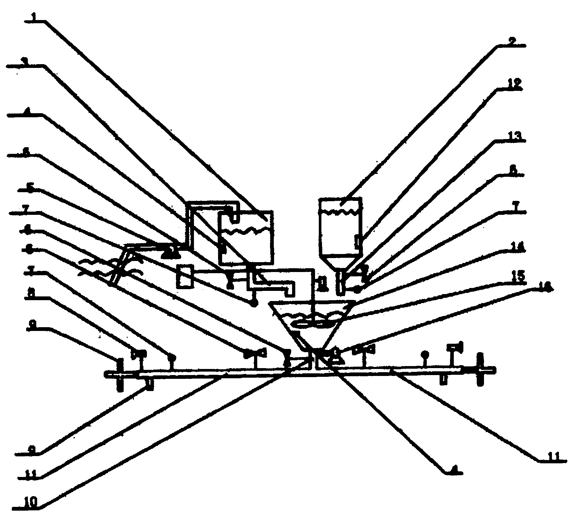
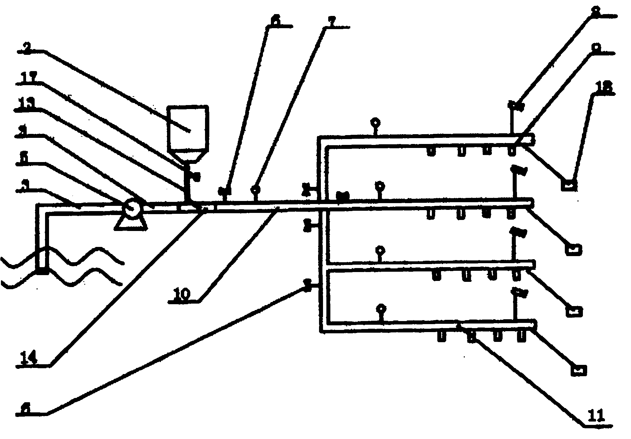
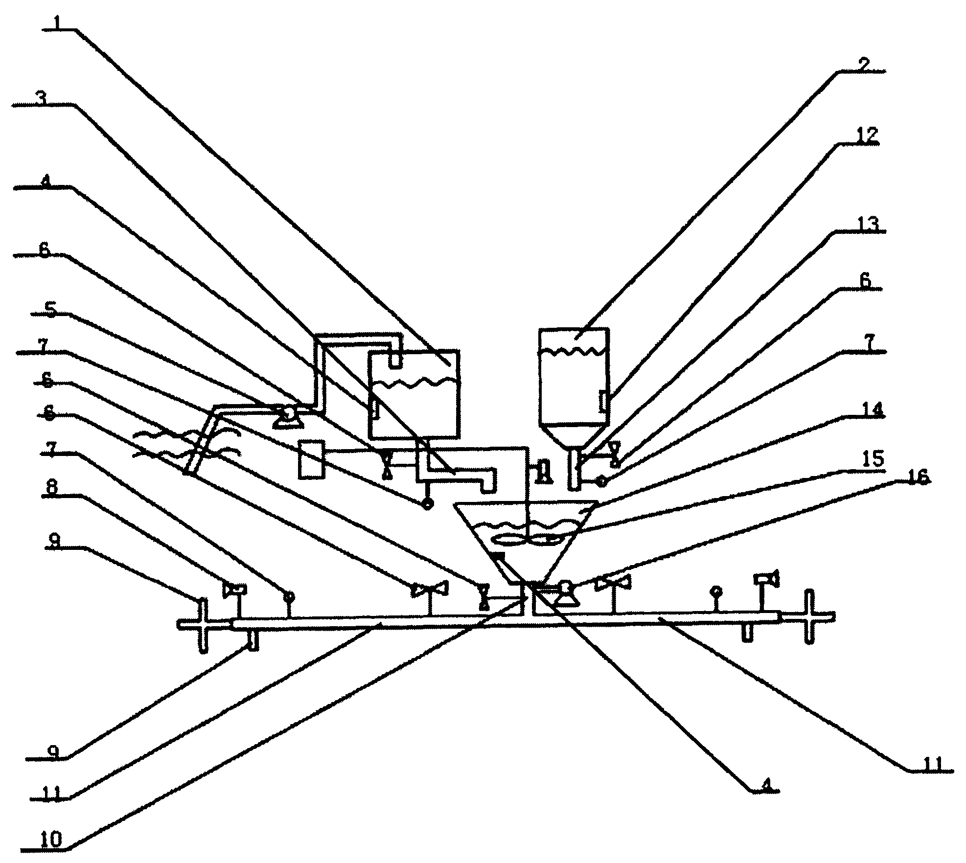
[0023] As shown in the figure, 1 is the water tank, 2 is the material storage device, 3 is the water inlet pipe, 4 is the water level sensor, 5 is the water pump, 6 is the adjustment device, 7 is the flow meter, 8 is the monitoring camera, 9 is the feeding device, 10 is the material mixing main pipe, 11 is the material mixing branch pipe, 12 is the feed sensor, 13 is the feeding pipe, 14 is the mixing device, 15 is the agitator, 16 is the pressurizing device, 17 is the electric control feeding valve, 18 is the water temperature and dissolved oxygen detectors.

[0024] figure 1 As an embodiment of the present invention, the water in the water tank 1 and the feed in the storage device 2 are mixed in the mixing device 14, then flow through the material mixing main pipe 10 to the material mixing branch pipe 11, and finally pass through the feeding device connected to the branch pipe 9. Feed it on the water surface of the fish pond. Among them, it should be noted that after the f...


PUM

PropertyMeasurementUnit
Lengthaaaaaaaaaa

Abstract

The invention discloses a low-carbon and environment-friendly feeding system. The feeding system adopting the structure of the invention breaks through the inertial thinking of the aquiculture breeding industry and creatively proposes a method of utilizing water as a feed transmission carrier so as to greatly decrease the feed packaging cost in one aspect, turn an aquiculture feed feeding process to be simple and high-efficiency and save mass labor in the other aspect. Meanwhile, the mixture of feed and water is transmitted so that a common automatic feeding machine can be canceled. The embodiment of the invention can decrease the cost of the breeding industry to a great extent, is more low-carbon and environment-friendly and has the advantages of low cost, good effect, packaging cost and mass labor cost saving, easy maintenance and little weather influence.

Description

technical field [0001] The invention relates to a feed feeding system in the aquaculture industry, in particular to a low-carbon and environment-friendly feeding system. Background technique [0002] In recent years, the aquaculture industry has developed rapidly, and there are more and more large-scale farms. In the rapid development of the aquaculture industry, some problems are becoming more and more prominent. As we all know, the aquaculture industry has great risks, and its capital investment is also large. It can be said that it is a capital-intensive industry. A little carelessness may lead to serious losses. The most important input in the breeding process is feed. According to statistics, in general fish farming, the feed cost for feeding fish accounts for 60% of the entire fish farming input. For example, the breeding period of crucian carp is 1 to 3 years. Under low stocking density and reasonable polyculture, through careful management, individuals can be raise...

Claims


Application Information

Patent Timeline
IPC IPC(8): A01K61/02
Inventor 秦琳玲
Owner 秦琳玲
Learn More