Aluminum alloy house

A technology of aluminum alloy and aluminum alloy beams, which is applied in the direction of roofs, building components, floors, etc., can solve the problems of heat insulation, sound insulation, waterproof, fire prevention, walls that cannot be dismantled or displaced, and restricted space layout freedom, etc. problems, to achieve superior seismic performance, outstanding advantages in assembly operations, and reduce the effect of temporary land use for operations

Active Publication Date: 2015-11-11
ALUHOUSE TECHGD CO LTD
View PDF5 Cites 20 Cited by
  • Summary
  • Abstract
  • Description
  • Claims
  • Application Information

AI Technical Summary

Problems solved by technology

Traditional houses limit the freedom of spatial arrangement due to the nature of the materials used
If the bay is too large, the thickness of the floor slab will be too large, and the cross-section of beams and columns will be too large, which will not only affect the aesthetics of the interior, but also increase the weight of the structure and increase the investment in civil engineering
It is planned to change the layout of the designed walls when moving in and decorating, but most of the walls cannot be dismantled or displaced, which not only increases the economic burden, but also increases the hidden dangers due to damage to the load-bearing walls
[0003] Traditional concrete buildings need to use a lot of concrete and bricks and tiles. The foundation construction takes a lot of soil, and it is necessary to dig mountains around the city, which consumes the precious resource of land and is not conducive to environmental protection.
[0004] The existing steel structure building is heavy, the material cost is high, and the basic cost is increased, which makes the investment of the whole project higher
In traditional buildings and steel structure buildings, heat insulation, sound insulation, waterproof and fire prevention measures are not taken for keels, wall panels, doors and windows and other components

Method used


Image

  • Aluminum alloy house
  • Aluminum alloy house
  • Aluminum alloy house

Examples


Embodiment Construction

[0057] The present invention will be described in detail below in conjunction with the accompanying drawings and embodiments.

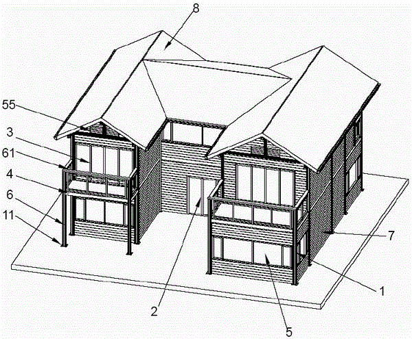
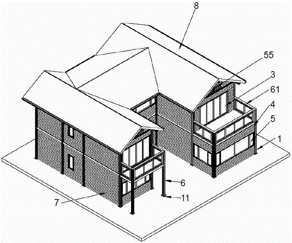
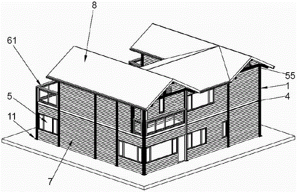
[0058] see Figure 1 to Figure 8 , the present invention provides an aluminum alloy house, which mainly consists of an aluminum alloy column 1, a column support 11, an aluminum alloy gate 2, an aluminum alloy door 3, an aluminum alloy beam 4, an aluminum alloy window 5, an aluminum alloy shutter 55, an aluminum alloy The balcony column 6, the aluminum alloy balcony railing 61, the aluminum alloy composite wall panel 7, the roof support column 10, the roof 8, and the bottom and second floor slabs 9.

[0059] The aluminum alloy columns 1 are arranged at intervals on the periphery and the inner ring of the house, and the aluminum alloy beams 4 are vertically and horizontally connected to the middle position of the outer aluminum alloy column 1 and the height of the inner ring aluminum alloy column 1, forming the ground floor and the second floor of the a...


PUM


Abstract

The invention relates to an aluminum alloy house. Aluminum alloy stand columns are arranged on the periphery and the inner ring of the house at intervals. Aluminum alloy beams are connected to the middle positions, in the height direction, of the aluminum alloy beams on the periphery and the inner ring of the house in a longitudinal and transverse segmented mode to form structures of the bottom layer and the second layer of the aluminum alloy house. Roof supporting columns are arranged on the aluminum alloy beams of the second layer. A roof is arranged on the roof supporting columns and the aluminum alloy stand columns. Three inwards-concave vertical face aluminum alloy combined wall plates are arranged in the middle of the aluminum alloy house in the foresight direction. An aluminum alloy gate is arranged in the middle of the front vertical face aluminum alloy combined wall plate, and therefore an inwards-concave space is formed in the aluminum alloy gate. Reverse Y-shaped sectional structures are arranged on the two sides of the roof. The front portion and the rear portion of the middle part of the roof are each in a slope shape. The two ends of each slope shape are connected with the middle rear portions of the reverse Y shapes on the two sides respectively. The aluminum alloy house is simple and firm in arrangement and connection structure, short in construction period, convenient to install, high in roof bearing strength and excellent in anti-seismic property.

Description

technical field [0001] The invention belongs to the field of building structures, in particular to a structure of an aluminum alloy house. Background technique [0002] In architectural design, it is always hoped to have a large-span space without vertical structure, which can be flexibly partitioned according to needs, so that the interior layout is diversified. Traditional houses limit the freedom of spatial arrangement due to the nature of the materials used. If the bay is too large, the thickness of the floor slab will be too large, and the cross-section of beams and columns will be too large, which will not only affect the aesthetics of the interior, but also increase the weight of the structure and increase the investment in civil engineering. It is planned to change the layout of the designed walls when moving in and decorating, but most of the walls cannot be dismantled or displaced, which not only increases the economic burden, but also increases the hidden dangers...

Claims


Application Information

Patent Timeline
Patent Type & Authority Applications(China)
IPC IPC(8): E04B1/00E04B1/24E04B7/02E04C2/284E04B5/02E04F15/18E04F15/06
CPCE04H1/04
Inventor 邝海峰
Owner ALUHOUSE TECHGD CO LTD
Why Eureka
Try Eureka