Cross flow gas-liquid two-phase flow cooling dedusting humidifying device

A technology of gas-liquid two-phase flow and humidification device, which is applied in the fields of air humidification system, heating method, climate sustainability, etc.

Inactive Publication Date: 2012-05-02
JAINGSU TOPSCI ENVIRONMENTAL PROTECTION TECH +2
View PDF7 Cites 1 Cited by
  • Summary
  • Abstract
  • Description
  • Claims
  • Application Information

AI Technical Summary

Problems solved by technology

[0003] The fan blades of the axial flow fan are all leaf type, and the gas phase flow generated in this way will have the following defects: 1. The air supply area is small, and the two-phase flow The action area is approximately conical with a small taper, so the water mist will be too concentrated in the conical area, which cannot produce a large cooling and dust removal area; 2. Although the axial flow fan can generate relatively high wind speed, but at the same time It also makes the recipient feel uncomfortable; 3. The atomizing nozzle can only be arranged along the circumference, or the mist source can only be arranged at the center of the fan blade (such as using a centrifugal atomizing device), no matter what way, it will make the The diffusion area of ​​water mist is limited; 4. The noise of axial flow industrial fans is large, and its safety often does not meet the requirements of public facilities

Method used


Image

  • Cross flow gas-liquid two-phase flow cooling dedusting humidifying device
  • Cross flow gas-liquid two-phase flow cooling dedusting humidifying device
  • Cross flow gas-liquid two-phase flow cooling dedusting humidifying device

Examples


Embodiment Construction

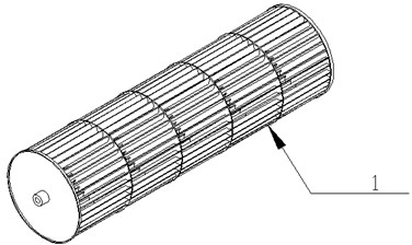
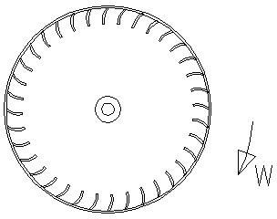
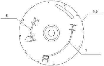
[0023] to combine Figure 1-5 , a specific embodiment of the present invention is described in detail.

[0024] The cross-flow gas-liquid two-phase flow cooling, dedusting, and humidifying device of the present invention (a gas-liquid two-phase flow air cooling, dusting, and humidifying device with approximately one-dimensional plane flow) is mainly used for cooling, dusting, and humidifying indoor and outdoor air , Therefore, the medium of gas phase flow is air, and the medium of liquid phase flow is water. The device comprises the gas phase flow generating device A and the liquid phase flow generating device B. The gas-phase flow generating device A is composed of the following main components: a cross-flow wind wheel 1, a motor 2, a bearing 3, a bearing seat 4, an upper side plate 5, a lower side plate 6, a deflector plate 7, and an air guide plate 8 , the guide plate 7 and the wind guide plate 8 are mechanically connected with the upper side plate 5 and the lower side pl...


PUM


Abstract

The invention discloses a cross flow gas-liquid two-phase flow cooling dedusting humidifying device, which comprises a gas phase flow generation device and a liquid phase flow generation device. The gas phase flow generation device is formed by main components including a cross flow wind wheel, a motor, a bearing, a lateral plate, a guide plate, an air induced plate and the like, and a gas-liquid two-phase flow approximate to a one-dimensional plane is produced. The liquid phase flow generation device is formed by main components including a power switch, an electric control device, an automatic controller, a decoder, an inflow solenoid valve, a three-level filter, a low pressure sensor, a high pressure sensor, a decompression solenoid valve, a high pressure water pump and the like. A rotating atomizing terminal is installed at the position close to the front end line of the air induced plate and parallel to the front end line of the air induced plate, and the liquid phase flow and the gas phase flow are mixed to form the gas-liquid two-phase flow. Due to the fact that the gas phase flow is approximately a plane flow, and sprayers are arranged in a line, action zone of the gas-liquid two-phase flow is approximately a plane with a certain thickness.

Description

technical field [0001] The patent of the present invention relates to a cross-flow gas-liquid two-phase flow cooling, dust removal and humidification device (a gas-liquid two-phase flow air cooling, dust removal and humidification device that approximates one-dimensional plane flow). The device can generate low-noise gas-liquid two-phase flow that approximates one-dimensional plane flow, and aims at reducing air temperature, reducing dust and increasing humidity. Background technique [0002] The two-phase flow fans currently appearing all use vane fans to supply air, which are axial flow industrial fans, such as the patented "Mobile Low Water Pressure Atomization Cooling Device" (Patent No.: 200820042183.3), which uses axial flow fans to dissipate water mist The fan blade of the axial flow fan is leaf type; the patent "centrifugal spray cooling humidifier" (patent number: 01226714.7) is to send the water mist generated by the centrifugal method from the axial flow fan, and ...

Claims


Application Information

Patent Timeline
Patent Type & Authority Applications(China)
IPC IPC(8): F24F5/00F24F6/14F24F11/02
CPCY02B30/545Y02B30/54
Inventor 阮鸿雁赵黎东拾亚男易威王坚伟陈松
Owner JAINGSU TOPSCI ENVIRONMENTAL PROTECTION TECH
Why Eureka
Try Eureka