

Stepped differential-velocity fluidized bed cooler
A fluidized bed cooler, a stepped technology, applied in the field of fluidized bed coolers, can solve the problems of poor cooling effect, high discharge temperature, uneven discharge particle temperature, etc., to achieve improved cooling efficiency, uniform temperature, good cooling effect
- Summary
- Abstract
- Description
- Claims
- Application Information
AI Technical Summary
Problems solved by technology
Method used
Image

Examples
specific Embodiment approach 1
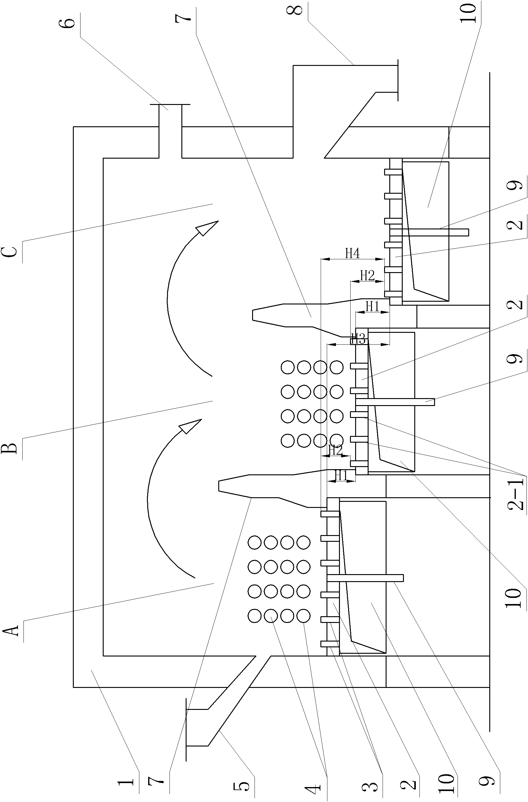
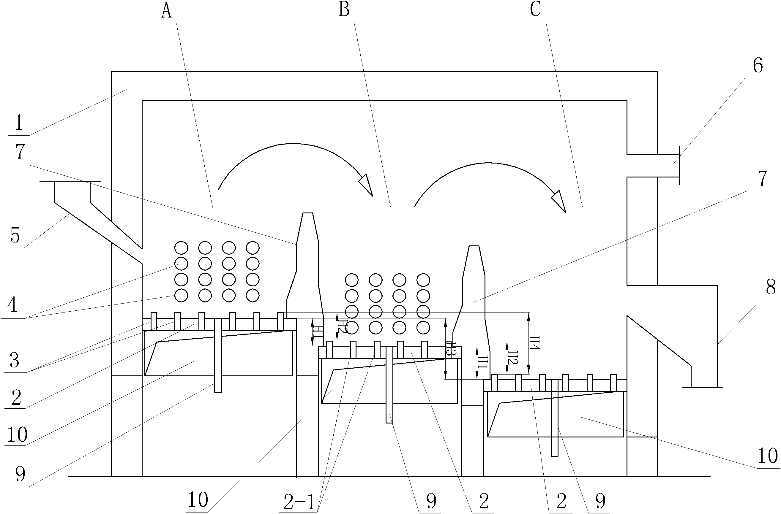
[0009] Specific implementation mode one: as figure 1 As shown, the stepped differential fluidized bed cooler of this embodiment includes a fluidized bed main body 1, a feed pipe 5, an exhaust pipe 6, a first discharge pipe 8, a plurality of second discharge pipes 9, a plurality of A wind chamber 10, a plurality of air distribution plates 2, a plurality of wind caps 3 and a plurality of overflow plates 7, one end of the feed pipe 5 is installed on the side wall of one end of the fluidized bed main body 1 and connected with the fluidized bed main body The inner cavity of 1 is connected, and the outer wall of the other end of the fluidized bed main body 1 is provided with an exhaust pipe 6 and a first discharge pipe 8 from top to bottom, and the exhaust pipe 6 and the first discharge pipe 8 All communicate with the inner cavity of the fluidized bed main body 1, the plurality of air chambers 10 are arranged in the inner cavity of the fluidized bed main body 1, and the plurality of...
specific Embodiment approach 2
[0011] Specific implementation mode two: as figure 1 As shown, the height difference H1 between two adjacent air distribution panels 2 in this embodiment is 180-550 mm. With such a design, there is a height difference between adjacent fluidized sub-beds, and the fluidized materials can enter the next stage smoothly. Other components and connections are the same as those in the first embodiment.
specific Embodiment approach 3
[0012] Specific implementation mode three: as figure 1 As shown, the height difference H2 between the air caps 3 on two adjacent air distribution panels 2 in this embodiment is 200-500 mm. This design ensures the fluidization height of adjacent fluidized sub-beds and prevents the exchange and back mixing of particles in adjacent fluidized sub-beds. Other compositions and connections are the same as those in the first or second embodiment.
PUM
 Abstract
Description
Claims
Application Information