Eureka AIR delivers breakthrough ideas for toughest innovation challenges, trusted by R&D personnel around the world.

Spatial phase-shifting unit, interferometry system applying same and phase-correcting unit

A technology of interferometry and interferometer, which is applied in the field of optical detection, can solve problems such as difficult correction of processing errors, influence of interferometry, and processing difficulties, and achieve high-precision dynamic measurement, dynamic measurement, and wide application value.

Inactive Publication Date: 2012-05-02
ZHEJIANG NORMAL UNIVERSITY
View PDF3 Cites 47 Cited by
  • Summary
  • Abstract
  • Description
  • Claims
  • Application Information

AI Technical Summary

Problems solved by technology

[0004] Although the above-mentioned polarization phase mask can introduce space carrier phase shift, its processing is more difficult, it is easy to produce processing errors, and it is not easy to correct processing errors, and processing errors will directly affect the accuracy of interferometric measurements. Therefore, the polarization The accuracy of the phase mask needs to be further improved; in addition, a processed polarization phase mask can only produce a specific spatial carrier phase shift distribution, which cannot be artificially modified, and its application will inevitably be limited

Method used


Image

  • Spatial phase-shifting unit, interferometry system applying same and phase-correcting unit
  • Spatial phase-shifting unit, interferometry system applying same and phase-correcting unit
  • Spatial phase-shifting unit, interferometry system applying same and phase-correcting unit

Examples


Embodiment Construction

[0029] In the following description, numerous specific details are set forth in order to provide a thorough understanding of the present invention. However, the present invention can be implemented in many other ways different from those described here, and those skilled in the art can make similar extensions without violating the connotation of the present invention, so the present invention is not limited by the specific implementations disclosed below.

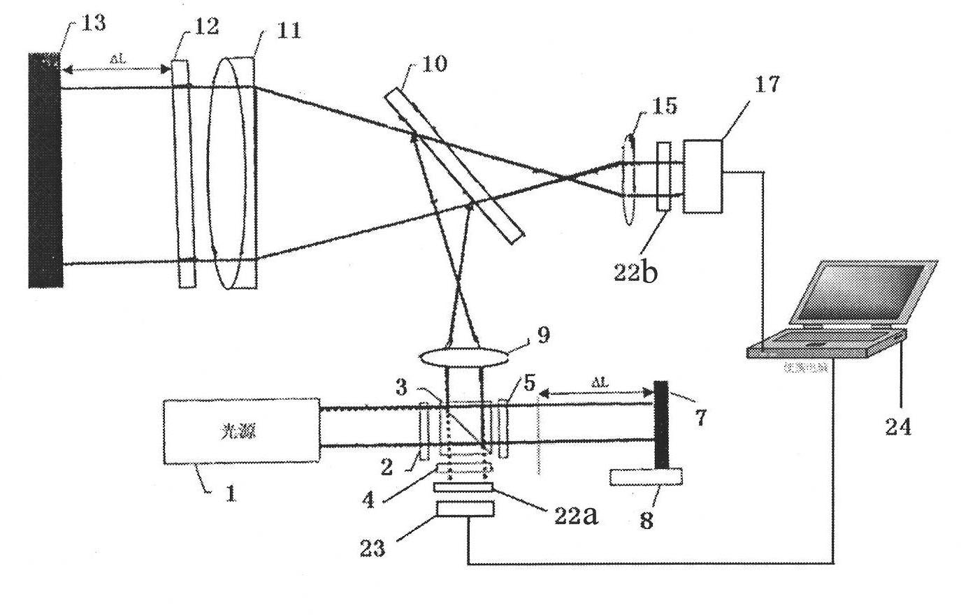
[0030] figure 1 is a schematic diagram of an embodiment of the interferometric device of the present invention. Please see figure 1 , in this embodiment, the interferometric device includes an orthogonally polarized light source, a phase-modulated spatial light modulator, an interferometer, and a light detection device. in,

[0031] The orthogonally polarized light source is used to generate linearly polarized light whose polarization states are orthogonal to each other, and the mutually orthogonally polarized light is c...


PUM


Abstract

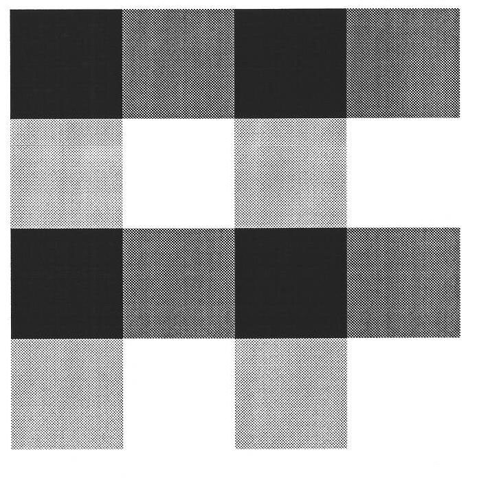
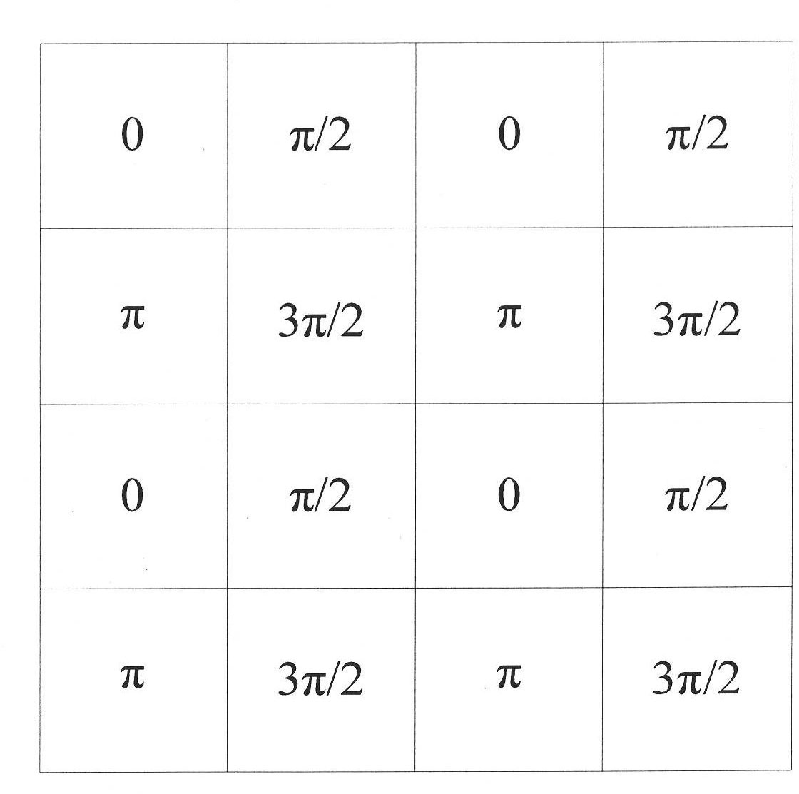
The invention provides an interferometry system, which comprises a unit, a phase modulation type spatial light modulator, an interferometer and a light detector; the unit is used for generating mutually orthogonal linearly polarized lights in the polarized state, and the mutually orthogonal linearly polarized lights are respectively called reference light and testing light; the phase modulation type spatial light modulator is arranged in the light path of the reference light or the testing light, and is used for changing spatial phase distribution before light waves; the spatial light modulator is provided with a plurality of pixels, each of which has specific phase distribution; the light, the phase of which is modulated by the spatial light modulator, is called modulated light, and the light which is not modulated is called unmodulated light; the interferometer is based on the modulated light and the unmodulated light to carry out interferometry; the coherent light generated by the interferometer is detected by the light detector; and moreover, the pixels of the spatial light modulator are corresponding to the pixels of the light detector. The system provided by the invention not only can carry out measurement during the phase shift distribution of a plurality of spatial carriers, but also can carry out high-precision dynamic measurement. The invention also provides a spatial phase-shifting unit and a liquid crystal spatial light modulator phase-correcting unit.

Description

technical field [0001] The invention relates to the technical field of optical detection, in particular to a spatial phase shift device. The invention also provides a phase correction device and an interferometric measurement device using the space phase shifting device. Background technique [0002] Interferometer has important application value in the surface shape detection of optical components. As far as the interferometry method is concerned, it can be divided into time-domain phase shift method, Fourier analysis method and space carrier phase shift method. The time-domain phase shift method has high measurement accuracy and is widely used in optical detection, but it requires at least three interferograms and is greatly affected by environmental vibrations, so it is not suitable for measurement in dynamic environments. The Fourier analysis method only needs a space carrier interferogram, so it is suitable for measurement in a dynamic environment, but the measurement...

Claims


Application Information

Patent Timeline
IPC IPC(8): G01B9/02
Inventor 徐建程
Owner ZHEJIANG NORMAL UNIVERSITY
Why Eureka
Eureka Blog
Learn More