Adjustable jitter measurement circuit based on self-reference signal

A measurement circuit and self-referencing technology, which is applied in the direction of pulse characteristic measurement, etc., can solve problems such as difficult calibration, poor measurement accuracy, and slow measurement speed, and achieve the effects of overcoming poor measurement accuracy, good measurement accuracy, and reduced measurement error

Inactive Publication Date: 2012-05-02
无锡东集电子有限责任公司
View PDF4 Cites 15 Cited by
  • Summary
  • Abstract
  • Description
  • Claims
  • Application Information

AI Technical Summary

Problems solved by technology

[0008] (1) Poor measurement accuracy: Due to the existence of process deviation, the delay time of each delay unit in Figure 1(a) cannot be controlled to be equal, thus affecting the accuracy of measurement;
[0009] (2) Difficulty in calibration: the circuit contains multiple sets of delay units, and it is not easy to achieve calibration;
[0010] (3) The measurement range is limited: when measuring signal jitter, it is necessary to input an ideal signal as a reference clock, which affects the measurement range;
[0011] (4) Low resolution and slow measurement speed: a large number of counters and phase detectors are used in the circuit, and the circuit area is large, which affects the resolution and measurement speed

Method used


Image

  • Adjustable jitter measurement circuit based on self-reference signal
  • Adjustable jitter measurement circuit based on self-reference signal
  • Adjustable jitter measurement circuit based on self-reference signal

Examples


Embodiment Construction

[0053] The preferred embodiments of the present invention will be described below in conjunction with the accompanying drawings. It should be understood that the preferred embodiments described here are only used to illustrate and explain the present invention, and are not intended to limit the present invention.

[0054] According to an embodiment of the present invention, such as Figure 2-Figure 6 As shown, a calibratable jitter measurement circuit based on a self-reference signal is provided.

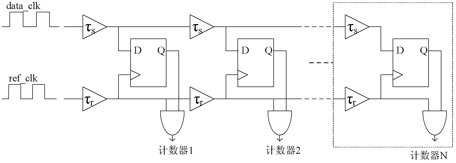
[0055] Such as figure 2 As shown, this embodiment includes a single-period sampling module, a first two-to-one data selector MUX1, a second two-to-one data selector MUX2, a first oscillating circuit, a second oscillating circuit, a phase detector, and a reset signal generating module with counter.

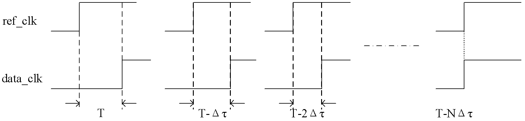
[0056] Among them: the single-cycle sampling module samples the clock signal Clock to be tested, and generates the En signal, S signal and Sd signal whose timing is one cycle behind in...


PUM


Abstract

The invention discloses an adjustable jitter measurement circuit based on a self-reference signal; an output end of a single-period collecting module is electrically connected with input ends of a first alternative data selector MUX1 and a second first alternative data selector MUX2; the output end of the first alternative data selector MUX1 is electrically connected with an input end of a first oscillating loop; the second alternative data selector MUX2 is electrically connected with the input end of a second oscillating loop; the output ends of the first oscillating loop and the second oscillating loop are both electrically connected with the input ends of phase discriminator; the output end of the phase discriminator is electrically connected with a reset signal generating module; and a counter is electrically connected with the second oscillating loop. The adjustable jitter measurement circuit based on self-reference signal, overcoming the disadvantages of low measurement accuracy, difficult correction, limited measurement scope, low resolution and low measurement speed in the prior art, has advantages of high measurement accuracy, convenient correction, wide measurement scope, high resolution and high measurement speed.

Description

technical field [0001] The invention relates to the field of electronic circuits, in particular to a calibratable jitter measurement circuit based on a self-reference signal. Background technique [0002] With the continuous progress of microelectronics technology and the continuous improvement of integrated circuit performance, the development of high-speed communication systems is getting faster and faster, and the requirements for clock frequency of high-speed communication system chips are also getting higher and higher. Phase Locked Loops (PLL for short) is one of the more commonly used clock generators at present. Clock jitter is an important parameter of PLL. The size of clock jitter in high-speed communication systems must be within the range specified by the design specification. Otherwise, it will lead to a series of problems such as system performance degradation, so the jitter measurement method is also more important. [0003] Currently, as shown in Figure 1(a)...

Claims


Application Information

Patent Timeline
Patent Type & Authority Applications(China)
IPC IPC(8): G01R29/02
Inventor 蔡志匡黄丹丹程赤杨军时龙兴
Owner 无锡东集电子有限责任公司
Why Eureka
Try Eureka