Heating power control circuit and control method

A technology for controlling circuits and heating power, applied in control/regulating systems, regulating electrical variables, instruments, etc., can solve problems such as overflow, and achieve the effects of extending service life, continuous heating, and continuous power output

Inactive Publication Date: 2012-05-02
MIDEA GRP CO LTD
View PDF7 Cites 11 Cited by
  • Summary
  • Abstract
  • Description
  • Claims
  • Application Information

AI Technical Summary

Problems solved by technology

But with the power as P, the equivalent power P is realized through the ope

Method used


Image

  • Heating power control circuit and control method
  • Heating power control circuit and control method
  • Heating power control circuit and control method

Examples


Embodiment Construction

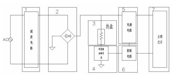
[0023] Such as figure 1 , the circuit module diagram of the heating power control of the present invention, including a filter circuit 1 connected to the mains, a rectifier circuit 2, a resistive heating device 3, a semiconductor power switch 4, a power supply circuit 5, a power switch control circuit 6 and a main control chip 7 , the input end of the rectifier circuit 2 is connected to the output end of the filter circuit 1, one end of the resistive heating device 3 is connected to the output end of the rectifier circuit 2, and the other end is connected to the semiconductor power switch 4, the main control chip 7, the semiconductor power switch 4 and The power switch control circuit 6 is electrically connected in turn, and the output terminal of the rectifier circuit 2 is connected to the power supply circuit 5 , and the power supply circuit 5 supplies power to the power switch control circuit 6 and the main control chip 7 .

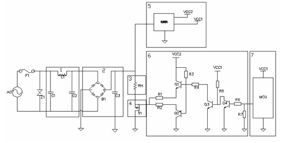
[0024] Such as figure 2 , an example diagram ...


PUM


Abstract

The invention relates to a heating power control circuit and a control method for a resistance heating component. The heating power control circuit comprises a filter circuit, a rectifier circuit, the resistance heating component, a semiconductor power switch, a power supply circuit, a power switch control circuit and a main control chip which are connected to a mains supply, the input end of the rectifier circuit is connected to the output end of the filter circuit, one end of the resistance heating component is connected to the output end of the rectifier circuit, the other end of the resistance heating component is connected to the semiconductor power switch, the main control chip, the semiconductor power switch and the power switch control circuit are successively electrically connected, the output end of the rectifier circuit is connected to the power supply circuit, and the power supply circuit supplies the power for the power switch control circuit and the main control chip. The mains supply is rectified to be a pulsatile direct current through the rectifier circuit, PWM (Pulse Width Modulation) wave forms generated by the main control chip are used for controlling operations of the power switch, adjusting the heating power of the resistance heating component, and controlling the continuous power change of the heating component, therefore, continuous heating of the heating component and continuous power output of a product can be achieved.

Description

technical field [0001] The invention relates to a heating power control circuit and a control method of a resistive heating element. Background technique [0002] Such as Figure 4 , the current power control method for products that use resistive components (resistance value R, unit: ohm) as the heat source is: the live wire (L line) of the mains is directly connected to one end of the resistive device, and the resistive device The other end is connected to one end of the relay, and the other end of the relay is connected to the neutral line (N line) of the mains, thus forming a heating circuit, and then the main control chip controls the opening and closing of the relay, so that the resistive device starts or stop fever. When the relay is turned on, the current I flows through the resistive device to make it heat up, and the product reaches the rated heating power P (unit: watt). When the relay is closed, the current flowing through the resistive device is zero, the resi...

Claims


Application Information

Patent Timeline
IPC IPC(8): G05F1/66
Inventor 梁三林卞在银黄兵麻百忠雷俊黄庶锋董远刘慧芳
Owner MIDEA GRP CO LTD
Why Eureka
Try Eureka