Tyre movement mechanism in X-ray tyre testing equipment

A technology for testing equipment and motion mechanisms, applied in measuring devices, material analysis using wave/particle radiation, instruments, etc., can solve the problems of high processing cost of worm gears, large resistance of worm gear transmission, and large heat generation of worm gear transmission. Achieve the effects of eliminating adverse effects, high detection repeatability, and simple installation and debugging

Active Publication Date: 2013-06-26
HEFEI MEIYA OPTOELECTRONICS TECH
View PDF1 Cites 1 Cited by
  • Summary
  • Abstract
  • Description
  • Claims
  • Application Information

AI Technical Summary

Problems solved by technology

Due to the tire's own weight, especially when testing heavy vehicle tires, the tire's own weight will cause the tire to deform, which affects the accuracy of the test
[0010] 3. Due to the high coordination requirements of worm gear and worm transmission, when there is a slight processing error or the installation is not in place, the resistance of worm gear and worm transmission is very large. Therefore, the processing cost of worm gear and worm is very high, and the installation and debugging are complicated, which is not convenient for popularization and application.
[0011] 4. The worm gear drive generates a lot of heat, and generally needs to be made of precious anti-friction metals to eliminate friction and heat, which further increases the cost of use

Method used


Image

  • Tyre movement mechanism in X-ray tyre testing equipment
  • Tyre movement mechanism in X-ray tyre testing equipment
  • Tyre movement mechanism in X-ray tyre testing equipment

Examples


Embodiment Construction

[0031] The content of the present invention will be described below in conjunction with specific embodiments.

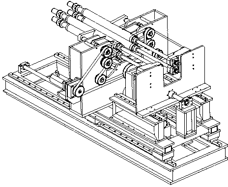
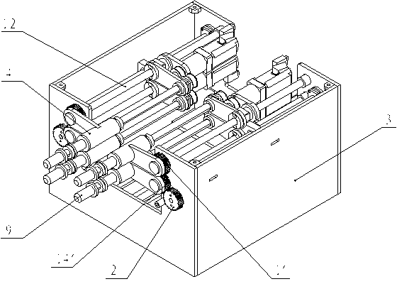
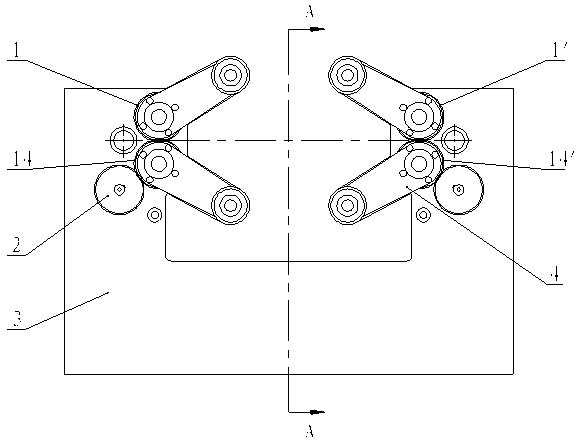
[0032] like figure 2 , image 3 and Figure 5 Shown, are respectively the tire kinematic mechanism assembly axonometric view and its front view and top view of the present invention, Figure 4 for image 3 A-A sectional view of the tire kinematic mechanism shown. The tire movement mechanism of the present invention includes a tire tire execution mechanism, a tire expansion mechanism and a tire rotation mechanism.

[0033] The main body of the tire support actuator is two sets of gears arranged symmetrically, and each set of gears works independently of each other without interfering with each other. Every group of gears comprises three gears, promptly each group of gears is provided with a driving gear 2 and the first driven gear 1, the second driven gear 14, and the driving gear 2 meshes with the second driven gear 14, and the second driven gear 14 and the sec...


PUM


Abstract

The invention relates to a tyre movement mechanism in X-ray tyre testing equipment. The invention belongs to the field of industrial nondestructive testing. The tyre movement mechanism comprises a tyre bracing execution mechanism, a tyre expending mechanism and a tyre rotating mechanism. The main body of the tyre bracing execution mechanism comprises two sets of gears arranged symmetrically, wherein the two sets of gears operate independently relative to each other. Each set of gears comprises a driving gear, a first driven gear, and a second driven gear. The first driven gears and the second driven gears operate under the driving of the driving gears. Tyre bracing tumblers are fixed on the first driven gears and the second driven gears. Cantilever supporting assemblies are arranged on the tyre bracing tumblers. Transmission sleeves are fixed on end faces of rotation sleeves. Tangential circle profile connection transmission is carried out between tyre bracing shafts and the transmission sleeves. With the mechanism provided by the invention, the smooth and stable operation of the tyre bracing tumblers is ensured, the testing precision is high, the processing cost is low, and the installation and adjustment are simple. The mechanism is suitable to be used for testing tyres with different sizes.

Description

technical field [0001] The invention relates to X-ray non-destructive testing equipment, in particular to a tire movement mechanism in the equipment for non-destructive quality testing of tire internal structures by using X-rays, and belongs to the field of industrial non-destructive testing. Background technique [0002] Tires play a pivotal role in the safety, freedom, load, speed, and comfortable driving of automobiles. Especially now that the operating speed is getting higher and higher, and the load is increasing, it is even more important for the quality of the tires. high demands. How to detect tires, especially the high-reliability non-destructive detection of tire internal defects has become particularly important. [0003] At present, the non-destructive testing of tires mostly adopts X-ray tire inspection system, in which the tire movement mechanism is an important part of the X-ray tire inspection system, which mainly realizes the functions of tire support, tire...

Claims


Application Information

Patent Timeline
Patent Type & Authority Patents(China)
IPC IPC(8): G01N23/00
Inventor 黄群英陈璋道奚正山
Owner HEFEI MEIYA OPTOELECTRONICS TECH
Why Eureka
Try Eureka