Detection device for electronic release of low-voltage apparatus, and control method

A technology of electronic release and detection device, which is applied in the direction of circuit breaker testing, etc. It can solve the problems that the results cannot be recorded in detail, and the time characteristics cannot be accurately measured, so as to improve the high cost of detection equipment, improve the low efficiency, and facilitate management. Effect

Active Publication Date: 2012-05-09
TIANJIN BAILI ELECTRIC CO LTD
View PDF5 Cites 3 Cited by
  • Summary
  • Abstract
  • Description
  • Claims
  • Application Information

AI Technical Summary

Problems solved by technology

[0002] At present, the known low-voltage circuit breaker releases are divided into magnetothermal and electronic releases. Electronic releases use transformers as signal acquisition devices, and complete circuit breaking through electronic circuit board circuits and magnetic flux converters based on soldered electronic components. The four-stage protection and other functions of the circuit breaker, because the electronic circuit board needs to collect electrical parameters such as various voltages and currents in the circuit breaker circuit through the transformer, it is generally replaced by a constant current generator and a voltage signal generator when testing or detecting Transformer, input signal to the electronic signal board, manually test various parameters and view various waveforms through the oscilloscope with reference to the debugging test file, and finally use the special time test equipment to test the time characteristics of the protection of the electronic release, because the equipment is for each It brings a lot of cost pressure for independent testing, and the time characteristics cannot be accurately measured without interconnection between various devices, and the results cannot be recorded in detail

Method used


Image

  • Detection device for electronic release of low-voltage apparatus, and control method
  • Detection device for electronic release of low-voltage apparatus, and control method
  • Detection device for electronic release of low-voltage apparatus, and control method

Examples


Embodiment Construction

[0017] In order to further understand the content, characteristics and effects of the present invention, the following examples are given, and detailed descriptions are as follows in conjunction with the accompanying drawings:

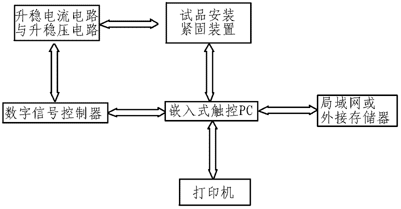
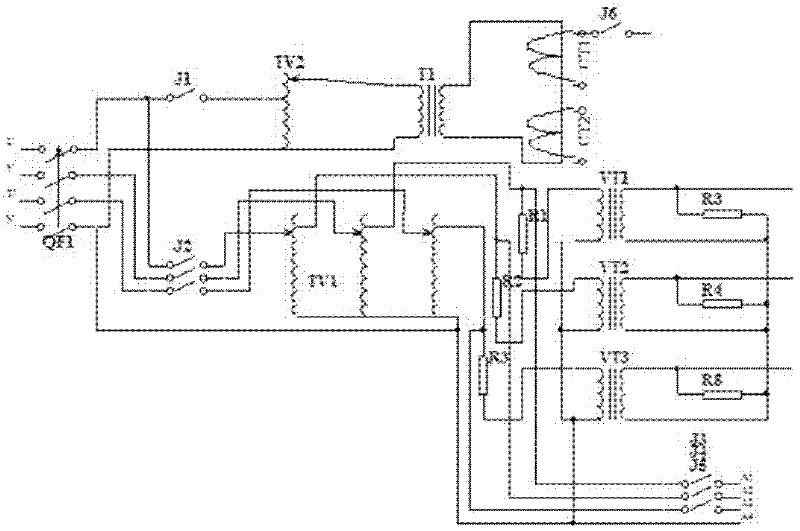
[0018] like figure 1 , 2 As shown, the boosting and stabilizing current circuit is connected to the input terminal of the single-phase step-up voltage regulator TV2 controlled by the stepping motor through the output port of the power supply QF1 through the relay J1, and the output terminal of the single-phase step-up voltage regulator TV2 is connected to the transformer T1 , the output end of the transformer T1 is short-circuited and connected in series in the loop of the transformer CT1 as the output detection signal and the transformer CT2 as the digital signal controller outputting the current signal for detection; the output end of the transformer CT1 is connected through the relay J6 The electronic release to be tested detects the current signal...


PUM


Abstract

The invention relates to a detection device for an electronic release of a low-voltage apparatus, and a control method. The detection device comprises a current and voltage signal port for detecting a to-be-detected electronic release, an embedded touch-control PC, a rising constant-current circuit and a rising constant-voltage circuit for providing rising constant-current and rising constant-voltage signals for a digital signal controller, the digital signal controller, a LAN (Local Area Network) or an external memory and a printer; the embedded touch-control PC transmits parameters pre-stored or set by users into the digital signal controller through a serial port COM; the digital signal controller controls a voltage regulator according to the acquisition result so as to regulate loop voltage and loop current to realize the set voltage regulation result, and the pressure regulating result is transmited to the embedded touch-control PC through the serial port COM; and the embedded touch-control PC inputs a test report into the LAN or the external memory through a USB (Universal Serial Bus) 2.0 and a network interface. Based on the modularized assembling mode, the detection device can detect various different electronic releases (electronic plates), so that detection efficiency is improved, cost on the detection equipment is reduced, detection is more reliable and has better consistency, and the detection device is convenient for management.

Description

technical field [0001] The invention belongs to a detection device, in particular to a detection device and a control method for a low-voltage electric appliance electronic trip unit. Background technique [0002] At present, the known low-voltage circuit breaker releases are divided into magnetothermal and electronic releases. Electronic releases use transformers as signal acquisition devices, and complete circuit breaking through electronic circuit board circuits and magnetic flux converters based on soldered electronic components. The four-stage protection and other functions of the circuit breaker, because the electronic circuit board needs to collect electrical parameters such as various voltages and currents in the circuit breaker circuit through the transformer, it is generally replaced by a constant current generator and a voltage signal generator when testing or detecting Transformer, input signal to the electronic signal board, manually test various parameters and ...

Claims


Application Information

Patent Timeline
Patent Type & Authority Applications(China)
IPC IPC(8): G01R31/327
Inventor 史祺暴凤蓉高辉王卫东
Owner TIANJIN BAILI ELECTRIC CO LTD
Why Eureka
Try Eureka