Supercharge Your Innovation With Domain-Expert AI Agents!

Photoelectric Sensors

A photoelectric sensor and sensor technology, applied in the field of photoelectric sensors, can solve the problems of pollution, position resolution is not improved, etc.

Active Publication Date: 2016-01-20
SICK AG
View PDF9 Cites 0 Cited by
  • Summary
  • Abstract
  • Description
  • Claims
  • Application Information

AI Technical Summary

Problems solved by technology

The grating detects small objects and can also get thickness information based on the degree of coverage, but does not have any information on where the object is located in the diameter of the beam
Therefore, the position resolution is not improved
In addition, the grating is not able to distinguish whether a reduction in signal is due on the one hand to being partially covered by objects or partially transparent objects or on the other hand to environmental conditions such as contamination of the beam shaping optics

Method used


Image

  • Photoelectric Sensors
  • Photoelectric Sensors
  • Photoelectric Sensors

Examples


Embodiment Construction

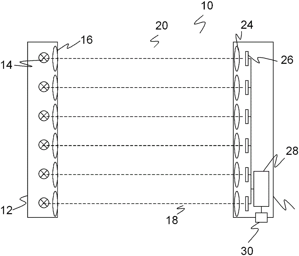
[0031] figure 1 A schematic cross-sectional view of a grating 10 is shown. The emitting unit 12 comprises a plurality of light emitters 14 arranged in a row, such as LEDs or lasers in the infrared or other spectral forms. The light of the light emitters 14 is collimated in the corresponding emission optics 16 and emitted as a light beam 18 through the monitoring region 20 to the receiving unit 22 . The light beam 18 impinges on a light receiver 26 corresponding to each light emitter 14 via the receiving optics 24 . The light receiver 26 is usually made as a photodiode, but could also be a position sensitive CCD or CMOS image sensor.

[0032] Unlike what is represented, the transmitting optics 16 and receiving optics 24 may include other elements, such as additional lenses, apertures, etc., and be designed such that the light beam 18 has a desired beam profile. The evaluation unit 28 is connected to the light receivers 26 and receives electrical reception signals which corre...


PUM


Abstract

The sensor has beam-forming optics which are assigned to the light transmitters and light receivers. The optics comprise an ellipsoidal, a triangular or a square-shaped geometry and an arrangement leading in a vertical direction to a monitored area so as to mutually overlap. An independent claim is included for method for determination of height and / or thickness of object with optoelectronic sensor.

Description

technical field [0001] The invention relates to a photoelectric sensor and a method for determining the height and / or thickness of an object according to the preambles of claims 1 and 13, respectively. Background technique [0002] A light barrier, sometimes called a light curtain, includes a plurality of emitting elements and corresponding receiving elements such that each pair of emitting elements and corresponding receiving elements forms a light barrier that detects the light barrier formed between the emitting and receiving elements. Whether the beam is interrupted. The transmitting element and the receiving element are incorporated in a transmitting unit and a receiving unit, respectively, which are installed opposite to each other. There are also gratings in which the transmitting and receiving elements are simultaneously accommodated in two opposite hybrid transmitting and receiving units. [0003] The concept of a light beam of individual emitting elements is idea...

Claims


Application Information

Patent Timeline
Patent Type & Authority Patents(China)
IPC IPC(8): G01V8/20
CPCG01V8/20
Inventor 丹尼尔·基耶茨于尔根·伯格阿克塞尔·豪普特曼甘特·希尔特
Owner SICK AG
Features
  • R&D
  • Intellectual Property
  • Life Sciences
  • Materials
  • Tech Scout
  • Unparalleled Data Quality
  • Higher Quality Content
  • 60% Fewer Hallucinations
Learn More