Power supply controller, electronic device, and method for controlling power supply

A technology of power controller and control circuit, applied in the direction of control/regulation system, instrument, electrical components, etc., can solve the problem of difficult to obtain output voltage and achieve the effect of reducing the impact

Inactive Publication Date: 2012-05-09
SOCIONEXT INC
View PDF6 Cites 5 Cited by
  • Summary
  • Abstract
  • Description
  • Claims
  • Application Information

AI Technical Summary

Problems solved by technology

Therefore, it is difficult to obtain an accurate output voltage

Method used


Image

  • Power supply controller, electronic device, and method for controlling power supply
  • Power supply controller, electronic device, and method for controlling power supply
  • Power supply controller, electronic device, and method for controlling power supply

Examples


Embodiment Construction

[0021] A switching power supply device according to various embodiments will be discussed. A comparator-type switching power supply is an example of a switching power supply capable of handling sudden load changes. The comparator-type switching power supply device receives a feedback voltage generated by dividing an output voltage of the switching power supply device, and controls a power supply by performing a switching operation when the feedback voltage decreases or increases with respect to a reference voltage.

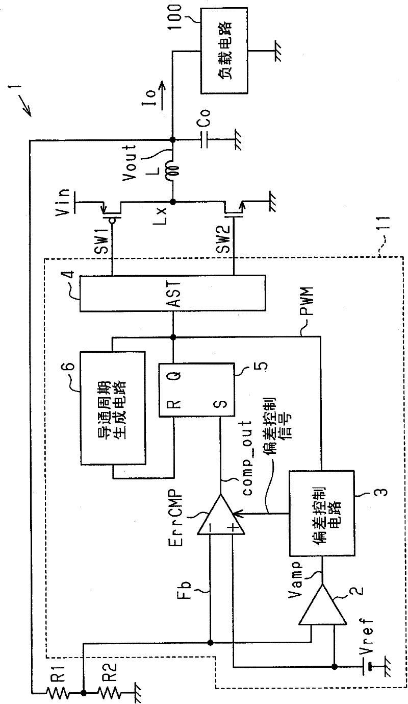
[0022] figure 1 is a block diagram of the switching power supply device 1, which is commonly shared by the embodiments described later.

[0023] The switching power supply device 1 includes: a switch SW1 , a switch SW2 , a resistor R1 , a resistor R2 , an inductor L, a capacitor Co and a switching power supply control circuit 11 . The switching power supply control circuit 11 controls the switch SW1 and the switch SW2, and includes a comparator ErrCMP, a deviati...


PUM


Abstract

A comparator type power supply controller that controls an output voltage. The power supply controller includes a comparator that compares a feedback voltage, which corresponds to the output voltage, with a reference voltage, wherein the comparator instructs power supply when the feedback voltage decreases when the feedback voltage decreases from the reference voltage. An offset application circuit is coupled to the comparator. The offset application circuit controls an input offset voltage of the comparator and decreases the input offset voltage as time elapses when the feedback voltage becomes lower than the reference voltage after the power supply ends. An amplifier amplifies a voltage difference of the feedback voltage and the reference voltage. The offset application circuit increases a change speed of the input offset voltage as the voltage difference increases in accordance with an output voltage of the amplifier.

Description

technical field [0001] The present invention relates to a comparator type power supply controller, electronic equipment and a method for the control power supply control. Background technique [0002] In order to improve the response to sudden load changes, a known switching power supply device amplifies the ripple component of the feedback voltage, and controls the output based on the comparison between the ripple component of the amplified output and a reference voltage (refer to Japanese Laid-Open Patent Publication No. .2010-35316). [0003] In another switching power supply device, current is supplied to a node to which a reference voltage is applied via a resistor. This adds a ramp voltage to the reference voltage. The output voltage is controlled by inputting the added voltage and the feedback voltage to the comparator (cf. US2005 / 00286269). [0004] However, in the comparator type switching power supply device, when control is performed so that the lower limit of ...

Claims


Application Information

Patent Timeline
Patent Type & Authority Applications(China)
IPC IPC(8): H02M3/157
CPCH02M3/156
Inventor 宫前亨
Owner SOCIONEXT INC
Why Eureka
Try Eureka