Light path tester

A tester and optical path technology, applied in the field of network communication, can solve the problems of high cost, cumbersome operation, inconvenient use, etc., and achieve the effect of saving maintenance costs and investment, reducing precision requirements, and achieving great economic benefits

Active Publication Date: 2012-05-09
CHINA TELECOM CORP LTD
View PDF4 Cites 10 Cited by
  • Summary
  • Abstract
  • Description
  • Claims
  • Application Information

AI Technical Summary

Problems solved by technology

The current optical test instruments basically use professional instruments, which require high precision, support multiple wavelengths, and are equipped with display screens and many operation keys, etc., but this also leads to complex structures, large

Method used


Image

  • Light path tester
  • Light path tester
  • Light path tester

Examples


Example Embodiment

[0035] The technical solutions of the present invention will be further described in detail below through the accompanying drawings and embodiments.
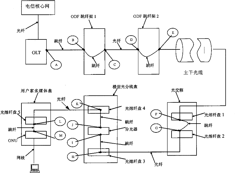
[0036] As mentioned earlier, during the actual investigation and experiment of FTTH installation and maintenance, the inventor found that the installation and maintenance personnel most concerned about the PON optical path test process is whether there is light coming from this section of the line, and whether the light intensity can meet the working of ONU equipment. Threshold value. Moreover, in the process of troubleshooting, 85% of the obstacles can be located and processed by judging whether there is an optical signal.

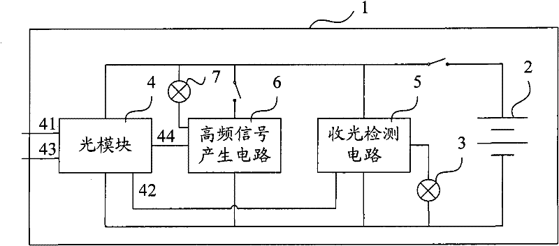
[0037] Based on this actual situation, the present invention redesigns the internal composition of the optical path tester, such as figure 2 Shown is a schematic structural diagram of an embodiment of the optical path tester of the present invention. In this embodiment, the optical path tester includes a housi...


PUM


Abstract

The invention relates to a light path tester, which comprises a shell body, a power supply device, a light signal display circuit, an optical module and a light receiving detection circuit, wherein the optical module is provided with a light input interface and an output level interface; the light receiving detection circuit is connected with the output level interface and the light signal display circuit; the power supply device supplies power to the optical module and the light receiving detection circuit; the optical module further comprises a light output interface and an input level interface for optical signal illumination; and the power supply device, the optical module and the light receiving detection circuit are all accommodated in the shell body. Compared with the existing optical tester, the light path tester adopts qualitative test and indicating lamp display to judge whether the optical signal exists or not, the requirements on test precision, test display and maintenance personnel quality are reduced, the manufacturing cost is far lower than the price of the existing optical tester, the requirement of light path detection can be satisfied, the maintenance cost and investment are also greatly saved, and furthermore, more economic benefit is produced.

Description

technical field [0001] The invention relates to network communication technology, in particular to an optical path tester applied to a passive optical network (Passive Optical Network, PON for short). Background technique [0002] With the rapid development of the Internet, network users' demand for network bandwidth is increasing day by day, and broadband users are not only satisfied with ordinary website browsing. The requirements of high-quality IPTV services for access bandwidth, user requirements for uplink speed, video conferencing, and high-speed downloads have gradually become mainstream applications. In order to meet the needs of the market, the core network of the communication network has undergone tremendous changes, while the traditional access network (the access network mainly refers to the network from the telecommunications room to the user end) that has been less changed has become the bottleneck of the entire network , various new broadband access technol...

Claims


Application Information

Patent Timeline
IPC IPC(8): H04B10/08H04B10/071
Inventor 杨春泽
Owner CHINA TELECOM CORP LTD
Why Eureka
Try Eureka