
DC (Direct Current) centralized power supply management method and device for LED (Light Emitting Diode) lights

A technology of LED lamps and centralized power supply, which is applied in the direction of electric lamp circuit layout, lighting devices, electric light sources, etc., can solve the problems of affecting the safe operation of the power grid, many devices, and inconvenient maintenance, and achieve convenient switching and maintenance and emergency, harmonic High content, good power quality effect

Active Publication Date: 2014-07-30
SHENZHEN TRIZ MASS ENERGY TECH
View PDF6 Cites 0 Cited by
  • Summary
  • Abstract
  • Description
  • Claims
  • Application Information

AI Technical Summary

Problems solved by technology

Since the AC / DC conversion contains switching high-frequency transformers and switching electronic devices, large high-order harmonics and low power factors will be generated, which will seriously affect the safe operation of the power grid, and even generate harmonic voltages that will affect the life of the lamp power supply.
The number of switching power supplies is the same as the number of lamps, and it is difficult to dissipate heat. They are scattered in each lamp, and there are many devices and fault points. The maintenance is inconvenient and cannot be managed centrally.
[0003] In addition, at present, the service life of LED lamps usually reaches 5-6 years, but because the service life of AC / DC power supply is generally about 3 years, the service life of LED lamps is greatly reduced. At the same time, due to the use in tunnels, it is dangerous to replace and repair lamps high sex

Method used


Image

  • DC (Direct Current) centralized power supply management method and device for LED (Light Emitting Diode) lights

Examples


Embodiment Construction

[0023] In order to make the object, technical solution and advantages of the present invention clearer, the embodiments of the present invention will be further described in detail below in conjunction with the accompanying drawings.

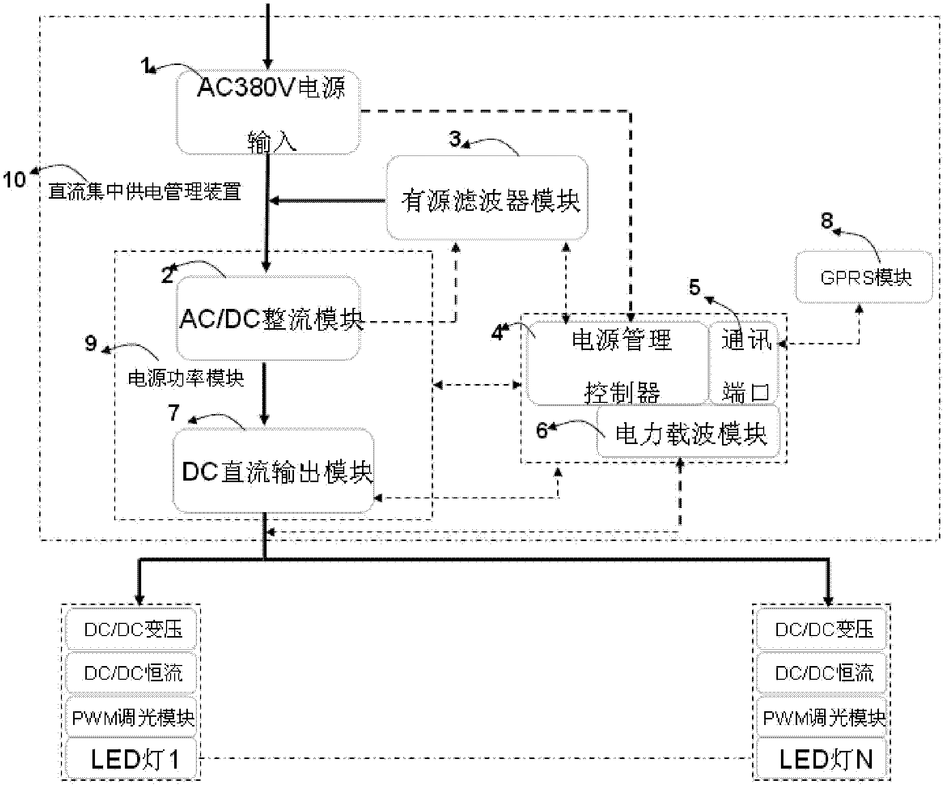
[0024] Such as figure 1 As shown, a DC centralized power supply management device for LED lights, the device includes a three-phase four-wire power input switch 1, an AC / DC rectifier module 2, an active filter module 3, a DC output module 7, a power management controller 4, The communication port 5 and the power carrier module 6, in which the AC / DC rectifier module 2 and the DC output module 7 form a power supply module 9, and multiple power supply modules 9 are installed in the tunnel LED lamp DC centralized power supply and management device 10 in a drawer-mounted manner. According to the size of the on-site load power, select the number of power supply modules, and design redundant modules as needed. Among them, the AC / DC rectifier module is...


PUM


Abstract

The invention relates to a DC (Direct Current) centralized power supply management method for LED (Light Emitting Diode) lights, the method comprises the following steps that: a three-phase four-wire power supply is divided into an A phase, a B phase and a C phase to enter each AC (Alternating Current) / DC rectification module to be rectified after the three-phase four-wire power supply enters a power switch of a DC centralized power supply management device for the LED lights; the three-phase four-wire power supply enters a DC output module for voltage stabilization and constant current control after being rectified, and the three-phase four-wire power supply is output and provided for LED use for each branch circuit through a 110-220V DC voltage. In the invention, a design that one high-power DC power supply is formed by multiple power supply-power modules and provides power supplies for multiple LED lights is adopted, therefore, the advantages of centralized power supply, few fault points and convenience for overhauling can be achieved, and the invention is particularly suitable for being used in tunnel LED lights; a drawer type design is adopted for power modules, therefore, when a certain power supply-power module is damaged, the power supply-power module can be achieved to be directly drawn out, and a new power module can be conveniently replaced, and the power modules can be designed to be redundant modules for standby according to the practical demands on site; combination is multi-module, switching, maintenance and emergency are convenient, and ultra-high-power transmission can be achieved.

Description

technical field [0001] The invention relates to the field of LED lamps and management, in particular to a method and device for managing DC centralized power supply of LED lamps. Background technique [0002] At present, the tunnel LED lighting is powered by 220V AC, and the AC / DC conversion circuit and constant current circuit are included in the lamp. Since the AC / DC conversion contains switching high-frequency transformers and switching electronic devices, it will generate large high-order harmonics and low power factor, which will seriously affect the safe operation of the power grid, and even generate harmonic voltages that will affect the life of the lamp power supply. The number of switching power supplies is the same as the number of lamps, and it is difficult to dissipate heat. They are scattered in each lamp, there are many components, and the number of fault points also increases. It is inconvenient to maintain and cannot be managed centrally. [0003] In additio...

Claims


Application Information

Patent Timeline
Patent Type & Authority Patents(China)
IPC IPC(8): H05B37/02
Inventor 王建平
Owner SHENZHEN TRIZ MASS ENERGY TECH
Learn More