Fuel filler door module
A fuel tank cover and segment technology, applied in the field of fuel tank cover modules
- Summary
- Abstract
- Description
- Claims
- Application Information
AI Technical Summary
Problems solved by technology
Method used
Image

Examples
Embodiment Construction
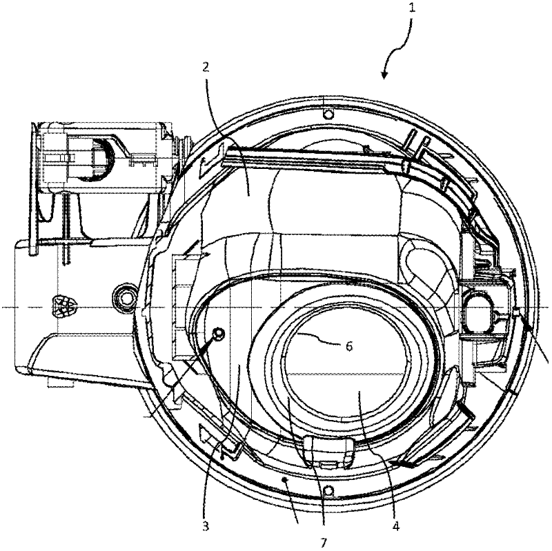
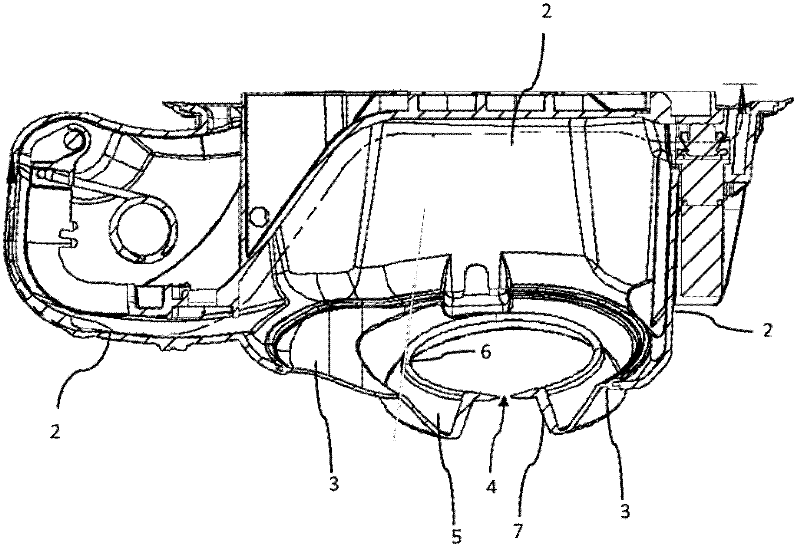
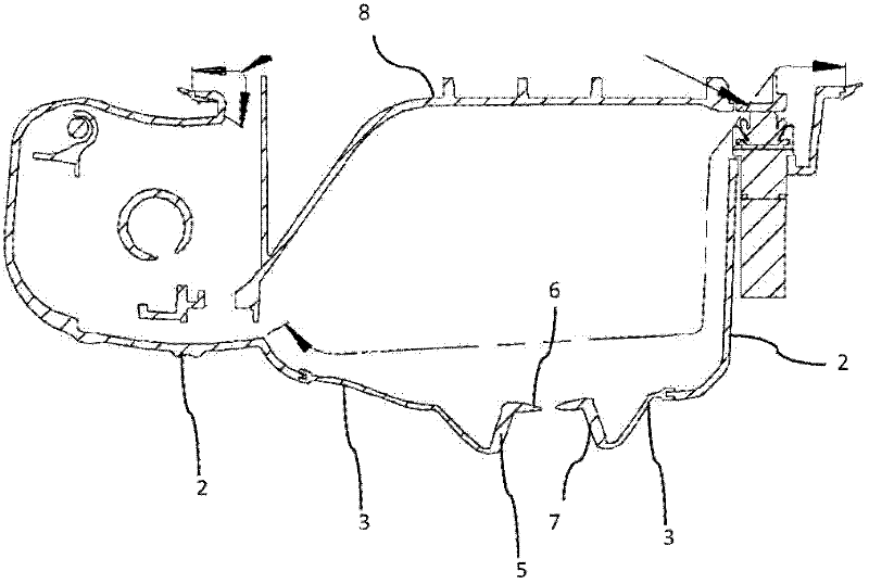
[0027] Figures 1 to 3 The tank cover module 1 shown in is constructed as a two-component figure 2 The upper vehicle outer side has the pot part 2 and the lower part, ie in the installed state pointing towards the vehicle inner side, has the floor section 3 . The transition zone between the bottom section 3 and the pot part 2 can be image 3 It is clearly seen in the cross-section of the . In this transition region, the pot part 2 is injection-molded on the inside and the outside by the base section 3 .
[0028] Both the can part 2 and the bottom section or bottom guard 3 can be produced by injection molding. The pot part 2 has a relatively hard and inelastic plastic material, such as polypropylene, whereas the bottom section 3 is provided with a relatively soft and elastically deformable plastic material, preferably EPDM (ethylene propylene diene rubber). The outer cup part 2 and the base section 3 together form the tank body 1 of the fuel tank cover module. In addition...
PUM
| Property | Measurement | Unit |
|---|---|---|
| Average roughness | aaaaa | aaaaa |
| Average roughness | aaaaa | aaaaa |
Abstract
Description
Claims
Application Information
 - R&D
- Intellectual Property
- Life Sciences
- Materials
- Tech Scout
- Unparalleled Data Quality
- Higher Quality Content
- 60% Fewer Hallucinations
Browse by: Latest US Patents, China's latest patents, Technical Efficacy Thesaurus, Application Domain, Technology Topic, Popular Technical Reports.
© 2025 PatSnap. All rights reserved.Legal|Privacy policy|Modern Slavery Act Transparency Statement|Sitemap|About US| Contact US: help@patsnap.com