Wave beam transmitting method of ultrasonic diagnostic apparatus and ultrasonic diagnostic apparatus

An ultrasonic diagnostic apparatus and ultrasonic technology, which are applied in the directions of sonic diagnosis, ultrasonic/sonic/infrasonic diagnosis, infrasound diagnosis, etc., can solve problems such as increasing the cost of probes

Active Publication Date: 2012-05-16
SHENZHEN MINDRAY BIO MEDICAL ELECTRONICS CO LTD
View PDF5 Cites 7 Cited by
  • Summary
  • Abstract
  • Description
  • Claims
  • Application Information

AI Technical Summary

Problems solved by technology

This is a measure to fundamentally improve the heating of the probe, but this

Method used


Image

  • Wave beam transmitting method of ultrasonic diagnostic apparatus and ultrasonic diagnostic apparatus
  • Wave beam transmitting method of ultrasonic diagnostic apparatus and ultrasonic diagnostic apparatus
  • Wave beam transmitting method of ultrasonic diagnostic apparatus and ultrasonic diagnostic apparatus

Examples


Embodiment 1

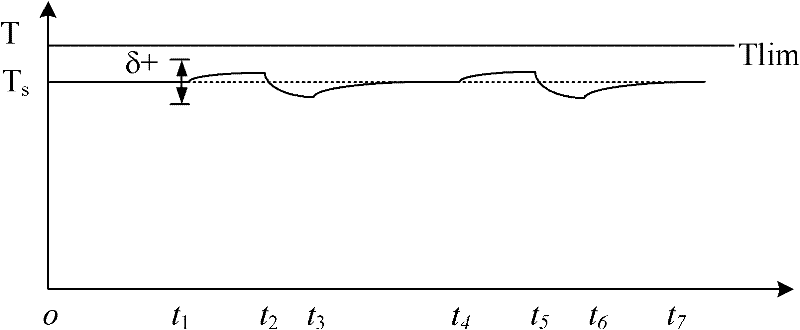
[0058] Please refer to Figure 4 , the combination of the high-power transmission mode and the stop-transmission mode is repeatedly executed according to the high-power transmission duration and the stop-transmission duration. The parameter setting unit calculates at least one parameter among the high transmission power and the high power transmission duration of the high power transmission mode and the stop transmission duration of the stop transmission mode according to the normal transmission power of continuous operation under the current transmission condition. For example, assuming that the pulse repetition frequency, emission aperture, emission waveform and scan width remain unchanged, only the emission voltage is changed, and the voltage of the normal emission power and the steady-state temperature rise T of the normal emission power are known. S and the allowable temperature fluctuation value δ, the t in the above formula (2) can be determined empirically 1 and t 2 ...

Embodiment 2

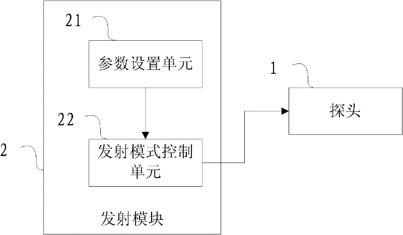
[0063] Please refer to Figure 6 , the ultrasonic diagnostic instrument includes a probe 1, a transmitting module 2 and a trigger signal generating module 3 for generating a trigger signal, the trigger signal generated by the trigger signal generating module 3 includes a trigger signal that is automatically generated repeatedly according to a set time, and a trigger signal according to a user's manual operation At least one of the generated trigger signal and the randomly generated trigger signal, the transmitting module 2 controls the array element transmission of the probe according to the combination of the set high-power transmission mode and the stop transmission mode after receiving the trigger signal Ultrasonic, when the stop emission reaches the stop emission duration, switch the emission mode back to the normal emission mode.

[0064] In this embodiment, the trigger signal is a trigger signal that is automatically generated repeatedly according to the set time, such a...

Embodiment 3

[0067] In this embodiment, the probe is still controlled to emit ultrasonic beams according to the combination of the set high-power emission mode and the stop emission mode according to the trigger signal, and the trigger signal is generated randomly or according to the user's manual operation. In this embodiment, the trigger signal generating module may include a trigger key, which may be set on the probe, and of course it may be set at any position of the ultrasonic diagnostic instrument that the doctor can easily touch, and the trigger signal is generated after the doctor operates it. Of course, in other embodiments, it may also be a trigger signal randomly generated by the trigger signal generation module.

[0068] From a clinical point of view, before using the high transmission power imaging mode, a good enough image quality is required for the diagnostician. The diagnostician can initially estimate the possibility of the lesion through the analysis in this mode, and use...


PUM


Abstract

The invention discloses a wave beam transmitting method of an ultrasonic diagnostic apparatus and the ultrasonic diagnostic apparatus. An array element of a probe is controlled to transmit ultrasonic according to the combination of a set high-power transmission mode and a set transmission-stop mode, at least one parameter of the high transmission power and high-power transmission duration of the high-power transmission mode and the transmission-stop duration of the transmission-stop mode is obtained by calculating the normal transmission power of the continuously working apparatus under current transmission conditions. According to the invention, not only can the quality of ultrasound patterns be improved, but also the surface temperature rising of the probe can be controlled to meet the requirements of IEC standard.

Description

technical field [0001] The invention relates to a medical device, in particular to an ultrasonic diagnostic instrument and a beam emitting method thereof. Background technique [0002] In 1992, with the support of the American Institute of Ultrasound in Medicine (AIUM) and the National Electrical Manufacturers Association (NEMA), the US Food and Drug Administration (FDA) made major adjustments to the acoustic output indicators of medical ultrasound. The FDA has relaxed the Ispta index of the sound output index to 720mw / cm2, and requires that the sound pressure and sound intensity parameters be converted into mechanical index (MI) and thermal index (TI) and displayed on the screen. In this way, for ultrasound manufacturers, the limitation of acoustic output becomes very wide, allowing ultrasound scanners with higher transmission power to be used in medical diagnosis. With the release of sound power indicators and the improvement of image quality requirements, the transmissio...

Claims


Application Information

Patent Timeline
IPC IPC(8): A61B8/00
CPCA61B8/00
Inventor 史志伟杨鹏飞
Owner SHENZHEN MINDRAY BIO MEDICAL ELECTRONICS CO LTD
Why Eureka
Try Eureka