Ultrasonic transducer control method and system

A technology of ultrasonic transducer and control method, which is applied in the directions of ultrasonic/sonic/infrasonic equipment control, ultrasonic/sonic/infrasonic diagnosis, sound wave diagnosis, etc. It can solve the problems of wasting labor costs and inaccurate measurement results, and achieve The effect of improving quality

Active Publication Date: 2016-04-20
VINNO TECH (SUZHOU) CO LTD
View PDF7 Cites 8 Cited by
  • Summary
  • Abstract
  • Description
  • Claims
  • Application Information

AI Technical Summary

Problems solved by technology

[0006] In order to meet the above requirements, in the prior art, the usual practice is to manually measure the surface temperature rise of the transducer with an external device such as a thermometer. This measurement method wastes labor costs, and at the same time, the measurement results are not very accurate.

Method used


Image

  • Ultrasonic transducer control method and system
  • Ultrasonic transducer control method and system
  • Ultrasonic transducer control method and system

Examples


Embodiment Construction

[0052] The present invention will be described in detail below in conjunction with the embodiments shown in the drawings. However, the embodiments do not limit the present invention, and the structural, method, or functional changes made by those skilled in the art based on these embodiments are all included in the protection scope of the present invention.

[0053] During the working process of the transducer, the electrical signal emitted by the ultrasonic transducer element is converted into an acoustic signal. In this process, corresponding thermal energy is generated, which further passes through the matching layer and lens and finally diffuses to the surface of the transducer .

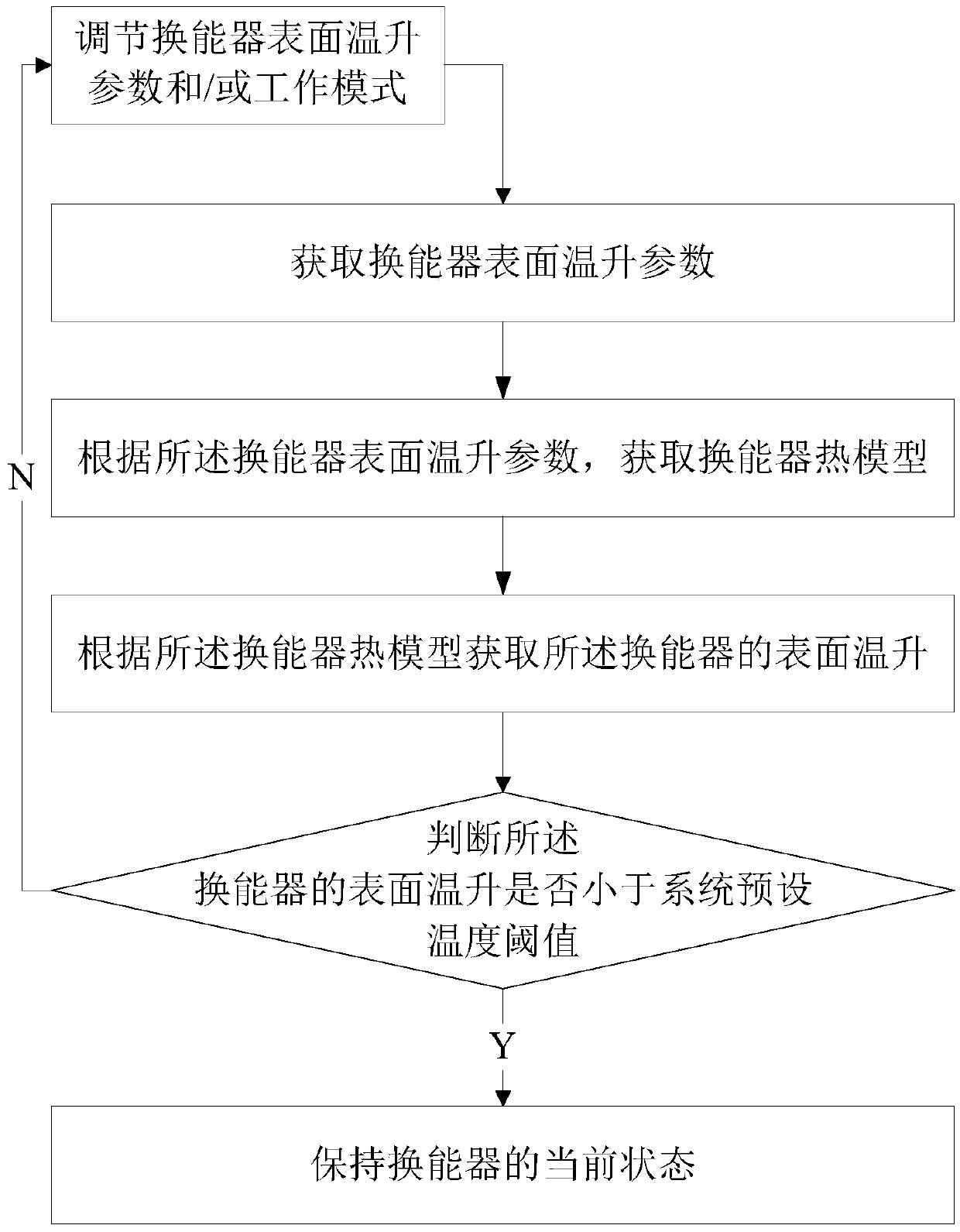
[0054] Such as figure 1 As shown, figure 1 This is an ultrasonic transducer control method provided by an embodiment of the present invention, and the method includes:

[0055] The surface temperature rise of the transducer is obtained according to the thermal model of the transducer.

[0056] In a pre...


PUM


Abstract

The invention provides an ultrasonic transducer control method and system. The method comprises: acquiring transducer surface temperature rise parameters, including: heat transfer coefficient, transmitting waveform coefficient, scanning coefficient, power supply transmitting voltage, and transmitting pulse repetition frequency; acquiring a transducer thermal model according to the transducer surface temperature rise parameters; the transducer thermal model is represented by a following formula; wherein deltaT represents the transducer surface temperature rise, kappa represents the heat transfer coefficient, phi(Waveform) represents the transmitting waveform coefficient, zeta(ImageAngle, F-number) represents the scanning coefficient, Vrms represents root-mean-square voltage of power transmission, and PRF represents the transmitting pulse repetition frequency. In the ultrasonic transducer control method and system of the invention, surface temperature rise of an ultrasonic transducer is automatically monitored according to current state of the ultrasonic transducer, meanwhile the surface temperature rise of the transducer can be precisely controlled according to monitoring results, and further, ultrasonic image quality is improved.

Description

Technical field [0001] The invention belongs to the technical field of ultrasonic imaging, and in particular relates to an ultrasonic transducer control method and control system. Background technique [0002] Ultrasound equipment has become one of the most widely used clinical diagnostic tools because of its non-invasive, real-time, convenient operation, low price and many other advantages. [0003] Ultrasonic transducer is a key component of ultrasonic equipment. It is an energy converter used to convert alternating electrical signals into acoustic signals within the ultrasonic frequency range or to convert acoustic signals in the external sound field into electrical signals; When the energy device is in the transmitting state, it converts electrical energy into mechanical energy and then mechanical energy into sound energy; in practical applications, it converts electrical signals into sound waves to propagate in the tissue to be measured; when the transducer is in the receiving...

Claims


Application Information

Patent Timeline
IPC IPC(8): A61B8/00
CPCA61B8/00A61B8/4483A61B8/54A61B2560/0266
Inventor 吴方刚陈惠人
Owner VINNO TECH (SUZHOU) CO LTD
Why Eureka
Try Eureka