
V-shaped stirring mixer

A mixer and stirring technology, which is applied in the direction of mixers, mixer accessories, mixers with rotating containers, etc., can solve the problems of high maintenance costs, low transmission efficiency, and short service life, and achieve high transmission efficiency and low maintenance costs. Low, long service life effect

Inactive Publication Date: 2012-05-16
金伟均
View PDF0 Cites 9 Cited by
  • Summary
  • Abstract
  • Description
  • Claims
  • Application Information

AI Technical Summary

Problems solved by technology

[0004] The technical problem to be solved by the present invention is to solve the technical problems of low transmission efficiency, uncompact structure, fast belt wear, short service life and high maintenance cost of the existing agitating V-type mixer.

Method used


Image

  • V-shaped stirring mixer
  • V-shaped stirring mixer
  • V-shaped stirring mixer

Examples


Embodiment 1

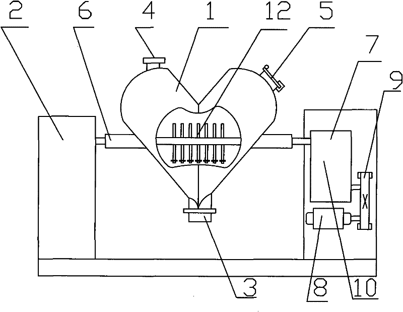
[0015] Embodiment 1: as figure 1 The shown first embodiment of the agitating V-type mixer of the present invention has a "V"-shaped mixing cylinder 1 and a seat 2, and the "V"-shaped mixing cylinder 1 is composed of two cylindrical cylinders, and the two cylindrical cylinders The lower end of the joint is provided with a discharge port 3, the upper end of one cylinder is provided with a feed port 4, and the upper end of the other cylinder is provided with a vacuum device 5, and two rotating shafts 6 are symmetrically arranged on the two cylinders. The shaft 6 is rotationally connected with the base body 2, and passes through the cavity of the rotating shaft 6 in the "V"-shaped mixing cylinder 1 and is fixedly connected with the base body 2 with an agitator 12, and the base body 2 is installed with a connecting rotating shaft 6 to drive The transmission mechanism 7 for the rotation of the mixing drum 1, the transmission mechanism 7 includes a motor 8, a connecting piece 9 and a...

Embodiment 2

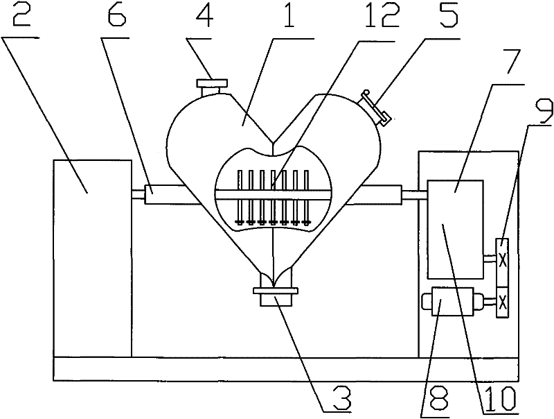
[0016] Embodiment 2: as figure 2 The shown second embodiment of the agitating V-type mixer of the present invention has a "V"-shaped mixing cylinder 1 and a seat 2, and the "V"-shaped mixing cylinder 1 is composed of two cylindrical cylinders, and the two cylindrical cylinders The lower end of the joint is provided with a discharge port 3, the upper end of one cylinder is provided with a feed port 4, and the upper end of the other cylinder is provided with a vacuum device 5, and two rotating shafts 6 are symmetrically provided on the two cylinders. The shaft 6 is rotationally connected with the base body 2, and a stirrer 12 is fixedly connected to the base body 2 through the cavity of the rotating shaft 6 in the "V"-shaped mixing cylinder 1, and the base body 2 is installed with a connecting rotating shaft 6 to drive The transmission mechanism 7 for the rotation of the mixing drum 1, the transmission mechanism 7 includes a motor 8, a connecting piece 9 and a gear reducer 10, ...


PUM


Abstract

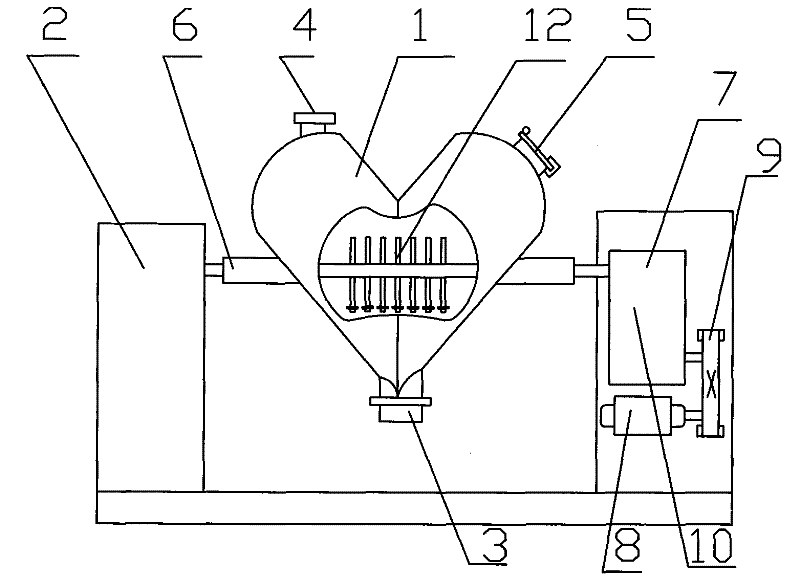
The invention relates to a V-shaped stirring mixer, which is provided with a V-shaped mixing barrel and a seat body, wherein the V-shaped mixing barrel consists of two cylindrical barrels; a discharging hole is formed at a lower end joint position between the two cylindrical barrels; the upper end of one of the cylindrical barrels is provided with a feeding hole, and the upper end of the other cylindrical barrel is provided with a vacuumizing device; two revolving shafts with hollow structures are symmetrically arranged on the two cylindrical barrels, and are rotationally connected with the seat body; a stirrer which passes through the cavities of the revolving shafts and is fixedly connected with the seat body is arranged in the V-shaped mixing barrel; a transmission mechanism which is connected with the revolving shafts and is used for driving the mixing barrel to rotate is arranged on the seat body, and comprises a motor, a connecting piece and a gear speed reducer; an output shaft of the gear speed reducer is connected with the revolving shafts through shaft couplings; and an input shaft of the gear speed reducer is connected with the output shaft of the motor through the connecting piece. The gear speed reducer is used for driving, so that a structure is more compact, the transmission efficiency is increased, the service life is prolonged, and the maintenance cost is reduced greatly.

Description

technical field [0001] The invention relates to a stirring V-shaped mixer. Background technique [0002] Stirring V-type mixer is widely used in pharmaceutical, chemical, food and other industries. It is a relatively general equipment for mixing more than two kinds of powdery and granular materials. The mixer has the characteristics of simple structure, easy operation, fast speed, high mixing efficiency, convenient maintenance and cleaning, and good mixing effect. Moreover, the machine can mix fine powder, clotted or more than two kinds of powder, and materials with a certain amount of water, and can also achieve a good mixing effect on ingredients with few additives. [0003] Most of the existing stirring V-type mixers use more than two stages of belt pulley deceleration transmission, although the structure of the belt transmission is simple, easy to manufacture, easy to install and maintain. However, the transmission efficiency of the belt drive is low, and the structure...

Claims


Application Information

Patent Timeline
IPC IPC(8): B01F9/08B01F15/00B01F29/64
Inventor 金伟均
Owner 金伟均
Learn More