Energy efficiency controlling method for refrigerating system

A technology of refrigeration system and control method, which is applied to refrigerators, refrigeration components, refrigeration and liquefaction, etc., can solve the problems of the operation efficiency of refrigeration units deviating from the highest point, waste of energy, lack of in-depth understanding of building operations, etc., so as to solve the problem of reducing variable flow The effect of cooling

Active Publication Date: 2012-05-16
SHENZHEN SHANNENG TECH
View PDF4 Cites 33 Cited by
  • Summary
  • Abstract
  • Description
  • Claims
  • Application Information

AI Technical Summary

Problems solved by technology

[0002] Existing or soon-to-be-designed building cold source equipment includes refrigeration units and heat pumps, etc. Since the manufacturers of these cold and heat source equipment consider the uniform use of equipment in a certain environment, the refrigeration host works at a certain state point with equipment design The highest efficiency point, but the designer did not have a deep understanding of the overall situation of the building operation. The site installation and the use of each building have their own characteristics. The heat load of the building is constantly changing with the indoor heat load and the outdoor environment. So how to use it? It is a contradictory thing for the same cold source equipment to run according to the characteristics of different buildings, and it is also a technical problem that needs to be solved for energy waste and energy saving of these cold and heat source equipment.
At the same time, when multiple refrigeration hosts are running jointly, how to control the number of consoles and set the cooling coefficient to make the energy efficiency of the system at the highest point at all times, the current control system has neither calculation method nor energy efficiency display
[0003] In addition, the control of the existing refrigeration unit is only a fixed setting control and the display of the operating status of the refrigeration main unit. If the system load is too high or too low, it can only rely on the operator to judge whether to increase the unit to start operation or stop operation. There is no basis for supply. The cooling load energy efficiency calculation dynamically adjusts the refrigeration parameters and automatically controls the increase and decrease of the unit to start and stop the operation, which may cause the operating efficiency of multiple refrigeration units to deviate from the highest point and the frequent increase or decrease of the unit operation

Method used


Image

  • Energy efficiency controlling method for refrigerating system
  • Energy efficiency controlling method for refrigerating system
  • Energy efficiency controlling method for refrigerating system

Examples


Embodiment Construction

[0044] In order to make the object, technical scheme and advantages of the present invention clearer, the following combination Figure 1-5 And embodiment, the present invention is described in further detail. It should be understood that the specific embodiments described here are only used to explain the present invention, not to limit the present invention.

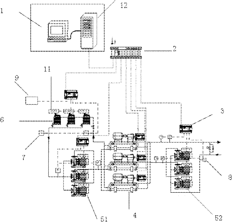
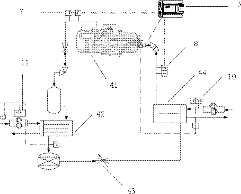
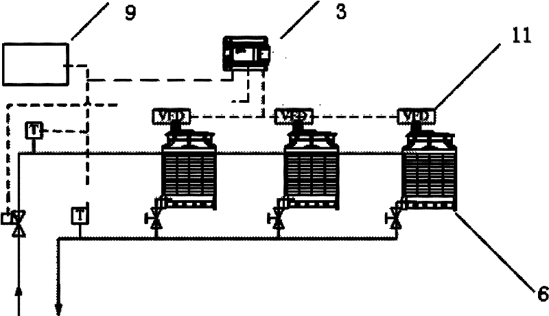
[0045] like Figure 1-3 As shown, the present invention forms a network of workstation 1, communication module 2, refrigeration unit and general chilled water pipe through a router; the workstation is provided with a server 12, and analyzes and processes all the information collected, so as to achieve the highest time for joint operation of multiple refrigeration units. Group control of energy efficiency points.

[0046] A communication module 2 is connected between the refrigeration unit and the workstation 1, and the communication module 2 is connected with the server 12 of the workstation 1 and the controller 3 of...


PUM


Abstract

The invention discloses an energy efficiency controlling method for a refrigerating system. The method comprises the following steps of: initializing the refrigerating system, and starting an automatic analysis operation mode according to the preset interval time; acquiring the operating parameter of each refrigerating host in real time, calculating the operating parameter when the energy efficiency of each refrigerating host or a cooling tower is optimal, and displaying the optimal value of the operating parameter on a monitoring interface of a work station; controlling a controller to regulate the operating parameter according to the optimal value by the work station, so that the energy efficiency of each refrigerating host is optimal; controlling the refrigerating system by a one-by-one increment/ reduction method, so that the energy efficiency of the refrigerating system is highest; and maintaining the optimal value of the operating parameter to operate the refrigerating system, and closing the automatic analysis operation mode till the next automatic analysis operation mode is started. By the method, automatic regulation of the energy efficiency of the refrigerating system and group control of a refrigerating unit can be realized.

Description

technical field [0001] The invention relates to an energy efficiency control method, in particular to an energy efficiency control method applied to a refrigeration system. Background technique [0002] Existing or soon-to-be-designed building cold source equipment includes refrigeration units and heat pumps, etc. Since the manufacturers of these cold and heat source equipment consider the uniform use of equipment in a certain environment, the refrigeration host works at a certain state point with equipment design The highest efficiency point, but the designer did not have a deep understanding of the overall situation of the building operation. The site installation and the use of each building have their own characteristics. The heat load of the building is constantly changing with the indoor heat load and the outdoor environment. So how to use it? It is a contradictory thing for the same cold source equipment to operate according to the characteristics of different buildin...

Claims


Application Information

Patent Timeline
Patent Type & Authority Applications(China)
IPC IPC(8): F25B49/02
Inventor 李先安
Owner SHENZHEN SHANNENG TECH
Why Eureka
Try Eureka