Electric current detection device and method thereof as well as electric current detection signal comparing unit and method thereof

A technology of current detection device and current detection circuit, which is applied in the direction of measuring device, measuring current/voltage, output power conversion device, etc., which can solve the problems of reducing reliability, complicating control circuit, increasing manufacturing cost, etc.

Active Publication Date: 2012-05-16
DELTA ELECTRONICS INC
View PDF5 Cites 26 Cited by
  • Summary
  • Abstract
  • Description
  • Claims
  • Application Information

AI Technical Summary

Problems solved by technology

In this way, image 3 The current detection circuit will complicate the contro

Method used


Image

  • Electric current detection device and method thereof as well as electric current detection signal comparing unit and method thereof
  • Electric current detection device and method thereof as well as electric current detection signal comparing unit and method thereof
  • Electric current detection device and method thereof as well as electric current detection signal comparing unit and method thereof

Examples


Embodiment Construction

[0095] Some typical embodiments embodying the features and advantages of the present invention will be described in detail in the description in the following paragraphs. It should be understood that the present invention is capable of various changes in different ways without departing from the scope of the present invention, and that the description and drawings therein are illustrative in nature rather than limiting the present invention.

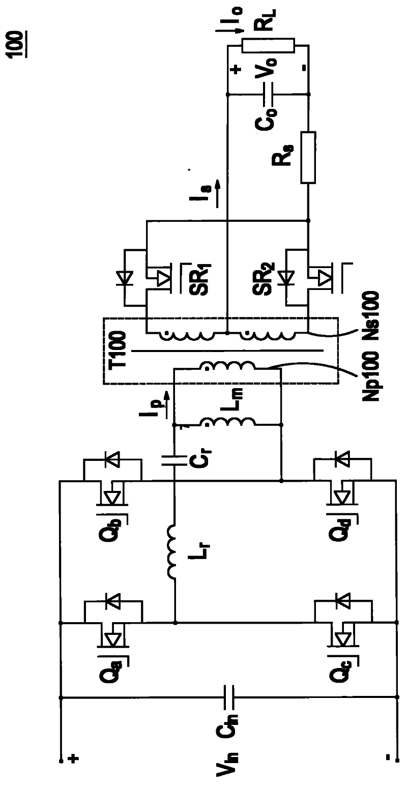
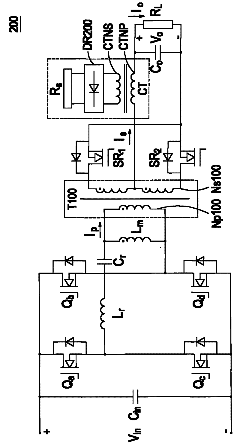
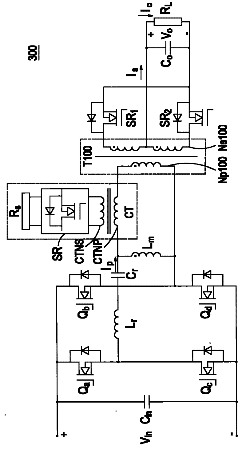
[0096] Figure 4 A comprehensive system block diagram showing the current sensing circuit of the present invention. Such as Figure 4 As shown, a power converter 400 includes a switch circuit 410, which is preferably a full-bridge LLC resonant converter, as shown in FIG. 5(A). However, the circuit structure of the switch circuit 410 is not limited to that disclosed in the embodiments herein, but can be any kind of converter topology. The power converter 400 further includes a current detection circuit 420 , a switch control circuit 43...


PUM


Abstract

The invention provides an electric current detection device, an electric current detection signal comparing unit, an electric current detection method and an electric current detection signal comparing method. The electric current detection device comprises an electric current detecting circuit, a control circuit, and a compensation circuit, wherein the electric current detecting circuit is used for detecting an electric current signal of a switching circuit so as to generate an electric current detecting signal, the control circuit is used for outputting an control signal, the compensation circuit is used for carrying out compensation on the electric current detecting signal according to the control signal; and the electric current detecting signal after compensation is compared with a constant current reference signal so as to output a constant current control signal. In addition, in the invention, on the other hand, the compensation circuit is set as compensation for the constant current reference signal, and the electric current detecting signal is compared with the constant current reference signal after compensation so as to output the constant current control signal. The electric current detection device, the electric current detection signal comparing unit, the electric current detection method and the electric current detection signal comparing method provided by the invention can apply to compensate an electric current detecting error caused by the switching circuit and the electric current detecting circuit, thereby obtaining the electric current detecting signal really reflecting the current output and having enough precision.

Description

technical field [0001] The invention relates to a power converter, in particular to a current detection device and a current detection and control method combined in the power converter. Background technique [0002] In electronic circuits, current signals are usually used as input signals for control circuits and protection circuits. The current signal can make the circuit work in a stable and reliable condition. Therefore, in order to understand the change of the current signal in the electronic circuit, an accurate current signal detection technology is needed to reflect the real circuit current. Current signals in typical electronic circuits include switch current, input current, and load current. Until now, there have been many direct and indirect current sensing techniques applied in various circuit topologies. figure 1 A known current detection circuit for detecting load current and a power converter 100 including the current detection circuit are shown. It should...

Claims


Application Information

Patent Timeline
IPC IPC(8): H02M3/28H02M3/335G01R19/00G01R19/165
Inventor 江剑吴其昆辛晓妮王彬吴洪洋
Owner DELTA ELECTRONICS INC
Why Eureka
Try Eureka