Photo current monitoring device

A monitoring device, photocurrent technology, applied in the direction of electrical components, electromagnetic wave transmission system, transmission monitoring/testing/fault measurement system, etc., can solve problems affecting TIA bandwidth, low noise characteristics, etc., to achieve small noise and bandwidth impact, monitoring Effect of accuracy and mirror circuit consistency and stability guarantees

Active Publication Date: 2011-09-14
XIAMEN UX HIGH SPEED IC
View PDF2 Cites 8 Cited by
  • Summary
  • Abstract
  • Description
  • Claims
  • Application Information

AI Technical Summary

Problems solved by technology

[0005] Furthermore, the problem of monitoring loss: the rear stage of the photodiode needs to be connected to a TIA (transimpedance amplifier). Since the TIA is a high-speed, low-noise circuit, the photocurrent monitoring device introduced cannot affect the bandwidth and low-noise characteristics of the TIA. Good enough isolation state, which is also one of the difficulties in monitoring circuit design

Method used


Image

  • Photo current monitoring device
  • Photo current monitoring device
  • Photo current monitoring device

Examples


Embodiment Construction

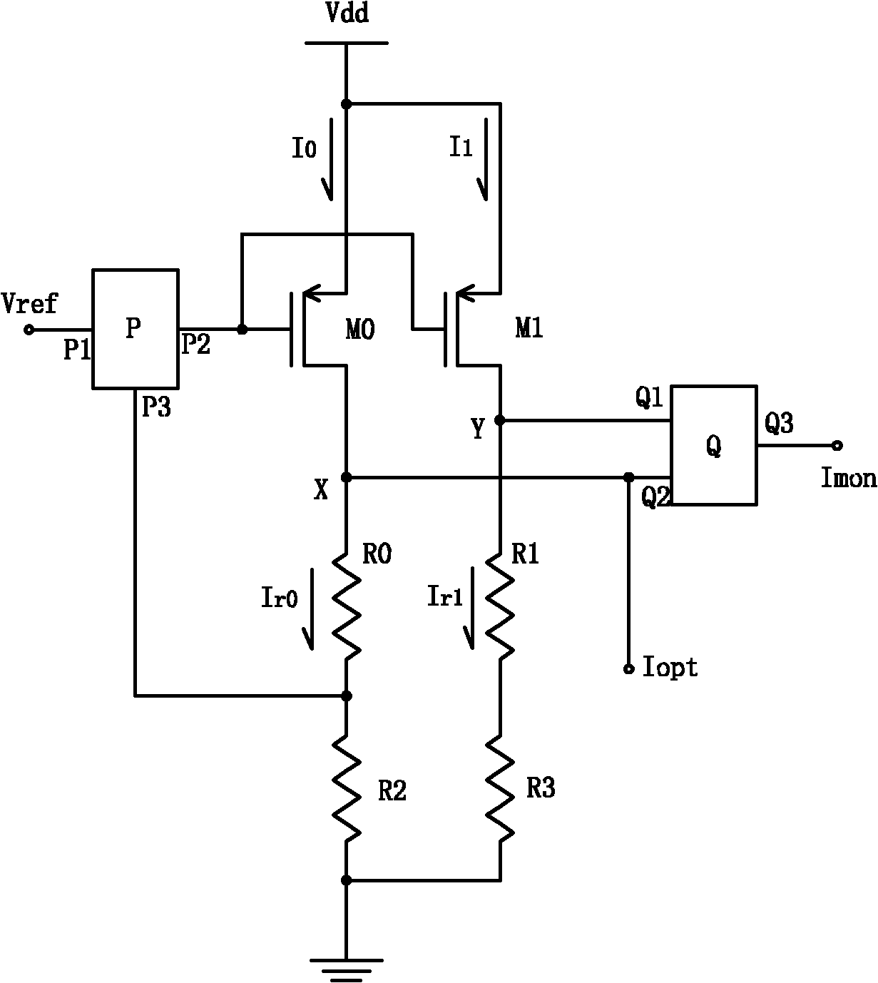
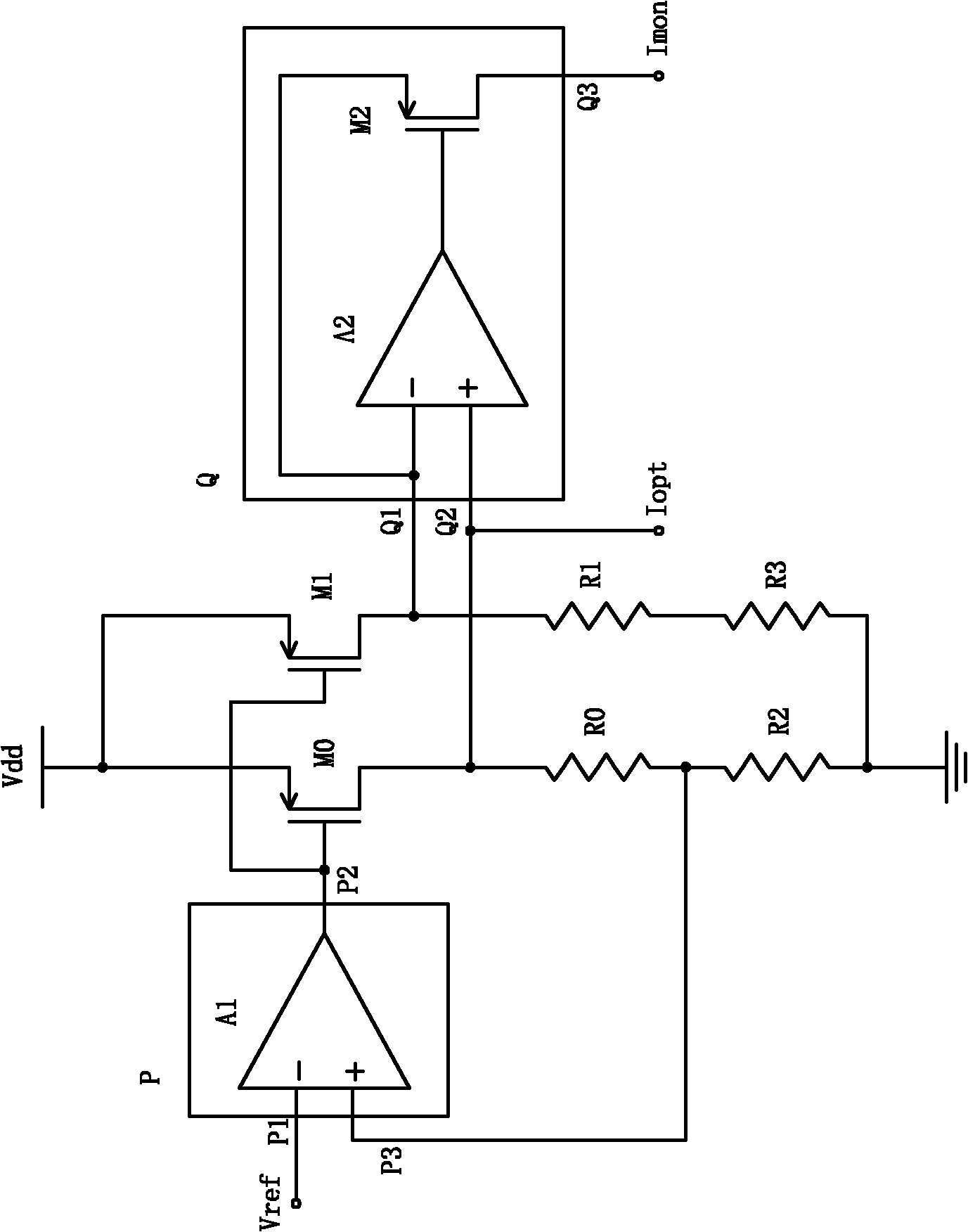
[0027] As shown in the figure, it is a schematic circuit diagram of Embodiment 1 of the present invention. The mirror monitoring circuit includes an adjustment module P, a first adjustment transistor M0, a second adjustment transistor M1 and four resistors R0 to R3; the adjustment module P has a reference input terminal P1, a clamp terminal P3 and an adjustment terminal P2. The clamp terminal P2 keeps the voltage across R2 stable and equal to the voltage Vref of the reference input terminal P1. Therefore, the voltage Vx of the X node is equal to:

[0028] Vx = Vref * ( 1 + R 0 R 2 )

[0029] Among them, since Vref is a reference voltage of 1.2V that is independent of temperature and power supply voltage generated by a reference bandgap generator, Vx is also very stable.

[0030] T...


PUM


Abstract

The invention discloses a photo current monitoring device used in high-speed fiber-optical communication, which is characterized by comprising a mirror image circuit and a clamp module, wherein the mirror image circuit consists of two parallel and consistent branch circuits; each branch circuit sequentially consists of a source electrode and a drain electrode of an adjusting pipe and two series resistors; the mirror image circuit further comprises an adjusting module and a clamp module; the adjusting module is used for forming a voltage-stabilizing circuit with the adjusting pipe; and the clamp module is used for clamping voltages at two ends of the mirror image circuit. The circuit integrates voltage-stabilizing bias and mirror image monitoring, thus providing a voltage-stabilizing circuit and a current source for a photodiode and ensuring the working state of the photodiode on one hand, and outputting monitoring current not influencing the photodiode so as to ensure the consistency and stability of the monitoring precision and the mirror image circuit, being capable of realizing muA level current monitoring, simultaneously ensuring enough precision of the photo current detectionin a wide range, and having small influence of a monitoring output end on transimpedance amplifier noise and bandwidth.

Description

technical field [0001] The invention relates to a photocurrent monitoring device. Background technique [0002] In modern optical fiber communication applications, real-time monitoring of optical pulse power transmitted by optical fibers is required to realize intelligent diagnosis of communication faults. To realize the monitoring of the received optical power, the photocurrent of the photodiode can be monitored, and then the optical power can be deduced and converted backwards. In this field, monitoring the photocurrent of the photodiode in the receiving component has the following difficulties: [0003] First, the monitoring photocurrent is small: accurate monitoring of the received optical power usually requires a circuit with high sensitivity. Taking the 1.25Gbps application as an example, such a transmission rate needs to monitor the optical power below -30dBm, which is converted into a photocurrent of 1μA level. To achieve accurate monitoring of the μA level current...

Claims


Application Information

Patent Timeline
IPC IPC(8): H04B10/08H04B10/07
Inventor 林少衡
Owner XIAMEN UX HIGH SPEED IC
Why Eureka
Try Eureka