Modeling method of using membrane humidifier to realize fuel-cell intake-air humidification

A membrane humidifier and fuel cell technology, applied in fuel cells, electrical components, instruments, etc., can solve the problems of transient response, difficulty in humidification efficiency stack influence, destruction of stack life, and reduction of true accuracy

Active Publication Date: 2018-11-23
TIANJIN UNIV
View PDF3 Cites 7 Cited by
  • Summary
  • Abstract
  • Description
  • Claims
  • Application Information

AI Technical Summary

Problems solved by technology

Although the existing models have explored the heat and mass transfer process in the membrane humidifier, the membrane humidifier is coupled with the fuel cell stack, and the high-humidity tail gas of the stack is used to humidify the low-temperature dry gas at the inlet end. It is also very difficult to study its transient response, humidification efficiency and its influence on the stack
This plays a decisive role in the selection of membrane humidifiers in actual product design. Unreasonable selection will not only reduce the performance of the stack, but may also seriously damage the life of the stack.
In addition, the existing membrane humidifier models usually only consider one of water vapor humidification or gas vapor humidification, and there may be liquid water in the exhaust gas at the cathode outlet of the stack, and the two humidification situations need to be considered comprehensively, otherwise it is true and accurate Sex will be greatly reduced

Method used


Image

  • Modeling method of using membrane humidifier to realize fuel-cell intake-air humidification
  • Modeling method of using membrane humidifier to realize fuel-cell intake-air humidification
  • Modeling method of using membrane humidifier to realize fuel-cell intake-air humidification

Examples


Embodiment Construction

[0064] The modeling process of the present invention will be further described through specific examples below. It should be noted that this calculation example is descriptive rather than restrictive, and does not limit the scope of protection of the present invention.

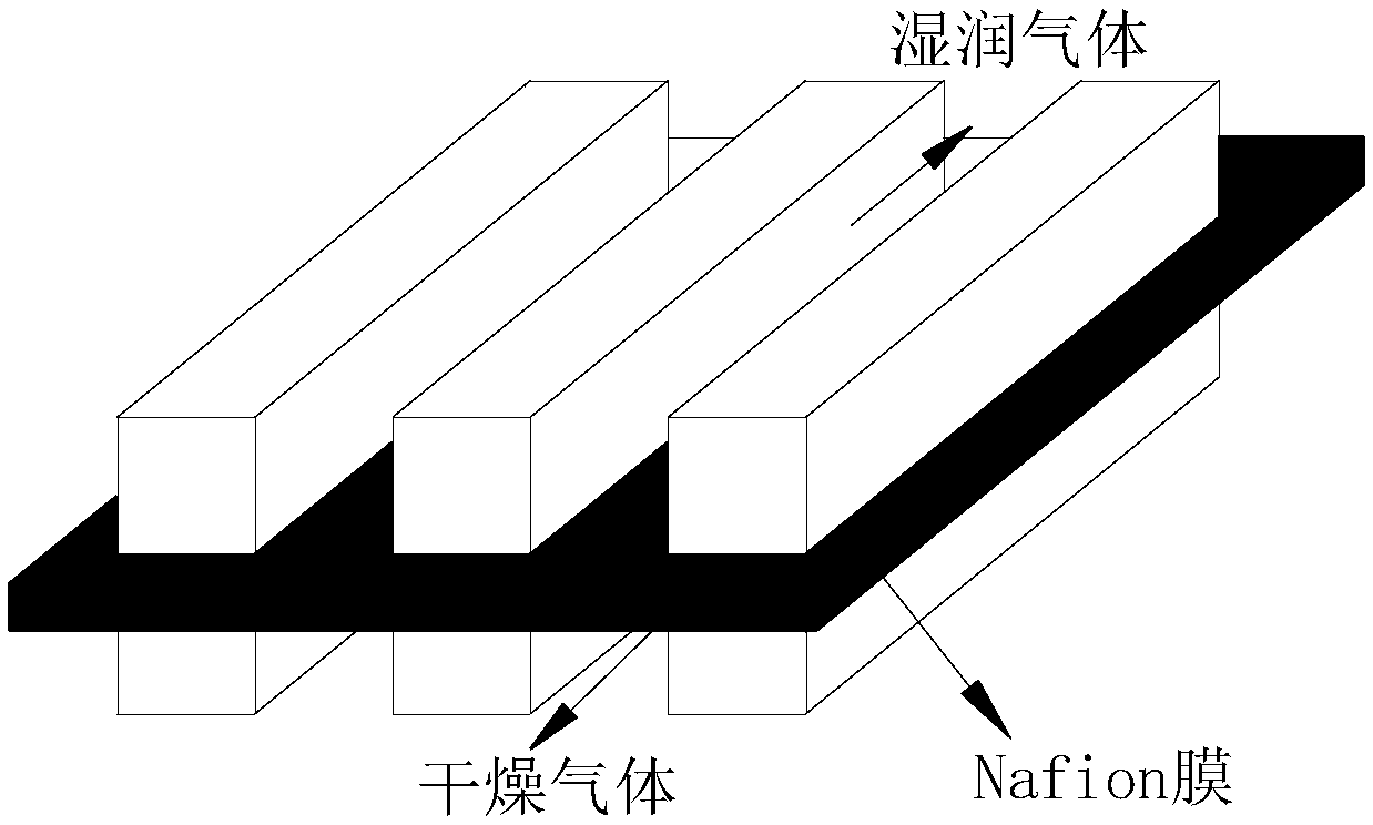
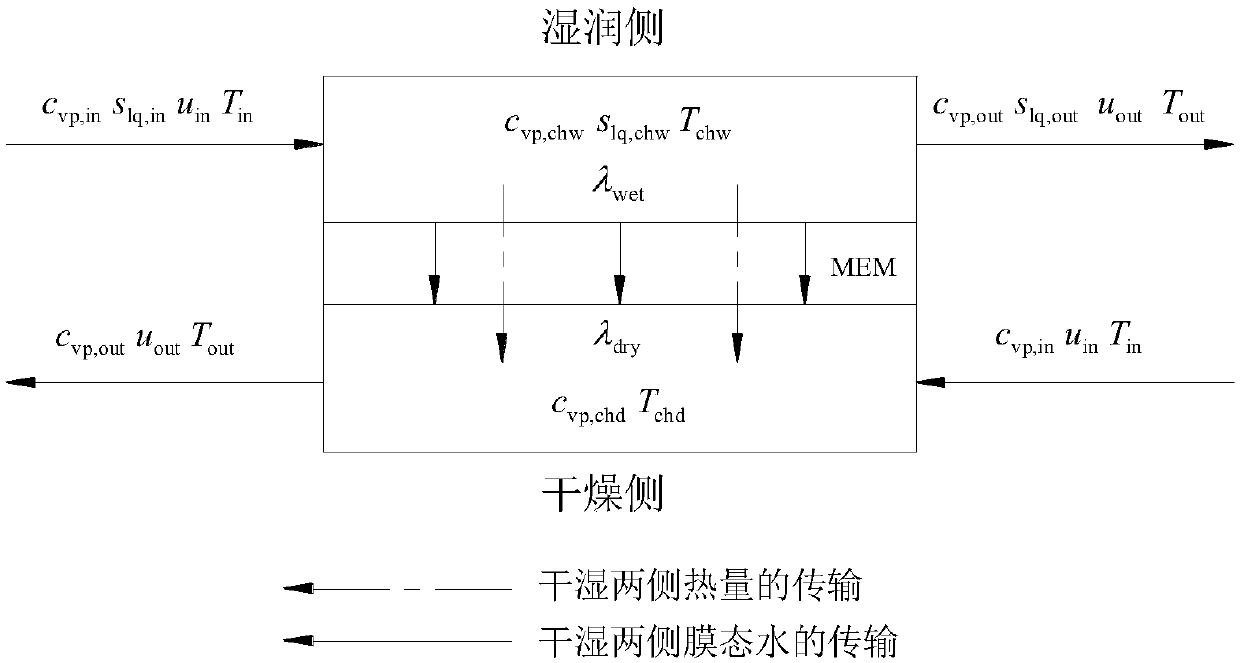
[0065] The physical structure of the flat membrane humidifier is as follows: figure 1 As shown, the main structure includes wet and dry side channels and proton exchange membrane. Humidification process such as figure 2 As shown, it can be roughly divided into the following stages: first, the water vapor in the wet side channel is absorbed by the membrane, then the water molecules diffuse to the dry side under the action of the concentration difference between the dry side and the wet side, and finally the water in the dry side membrane and The water vapor in the flow channel establishes an equilibrium state, and then infiltrates the air. The above water transfer process is accompanied by heat transfer.

[...


PUM

PropertyMeasurementUnit
areaaaaaaaaaaa
thicknessaaaaaaaaaa

Abstract

The invention provides a modeling method of using a membrane humidifier to realize fuel-cell intake-air humidification. A transient simulation model of the one-dimensional flat membrane humidifier isestablished. Governing equations of the model include four conservation equations of a water content in membrane, water vapor in a flow channel, liquid water in a wet side flow channel and energy. High-heat high-humidity exhaust gas of a fuel cell stack is used to humidify desiccated low-temperature reaction gas at a humidification inlet, and a water-heat coupling transfer process inside the humidifier, phase change processes among the water vapor, the liquid water and membrane water and a combined humidification function of water and gas are fully considered. The model is based on a display format updating algorithm, the governing equations are solved at a center of each layer, calculation efficiency is high, and sufficient model accuracy can be guaranteed. The membrane humidifier model can realize coupling with the electricity stack, and a perfect humidification system is constructed through setting of boundary conditions to be used as a numerical simulation tool of heat and mass transfer analysis, structure optimization and type selection of a system, and has very high guiding significance for actual product development.

Description

technical field [0001] The invention is applied to the field of proton membrane fuel cells, and in particular relates to a model building method of a one-dimensional transient flat-plate membrane humidifier. technical background [0002] Proton exchange membrane fuel cell (PEMFC), as a high-efficiency, low-pollution energy conversion device, has attracted widespread attention from scholars at home and abroad when the energy crisis and environmental pollution problems are becoming more and more prominent. When the proton exchange membrane fuel cell is working, the H produced by the anode reaction + In the process of passing through the proton exchange membrane to the cathode, each H + It will drag 1 to 5 water molecules, resulting in the loss of water in the membrane on the anode side. Although the water generated on the cathode side will diffuse to the anode to a certain extent under the action of the concentration gradient, the membrane on the anode side may still be in a ...

Claims


Application Information

Patent Timeline
Patent Type & Authority Applications(China)
IPC IPC(8): G06F17/50H01M8/04828
CPCH01M8/04828G06F30/367Y02E60/50
Inventor 杜青杨子荣范立超刘展睿焦魁
Owner TIANJIN UNIV
Why Eureka
Try Eureka