Cutting tool

A technology of cutting tools and cutting blades, which is applied in the direction of cutting blades, milling cutting blades, and tools used in lathes, etc. It can solve the problems of increased screw head wear and achieve the effects of cost saving, small size, and simple operation

Active Publication Date: 2012-05-16
CERATIZIT AUSTRIA GES
View PDF9 Cites 8 Cited by
  • Summary
  • Abstract
  • Description
  • Claims
  • Application Information

AI Technical Summary

Problems solved by technology

Such a multi-point contact between the screw head and the through-hole leads to increased wear of the screw head

Method used


Image

  • Cutting tool
  • Cutting tool
  • Cutting tool

Examples


Embodiment Construction

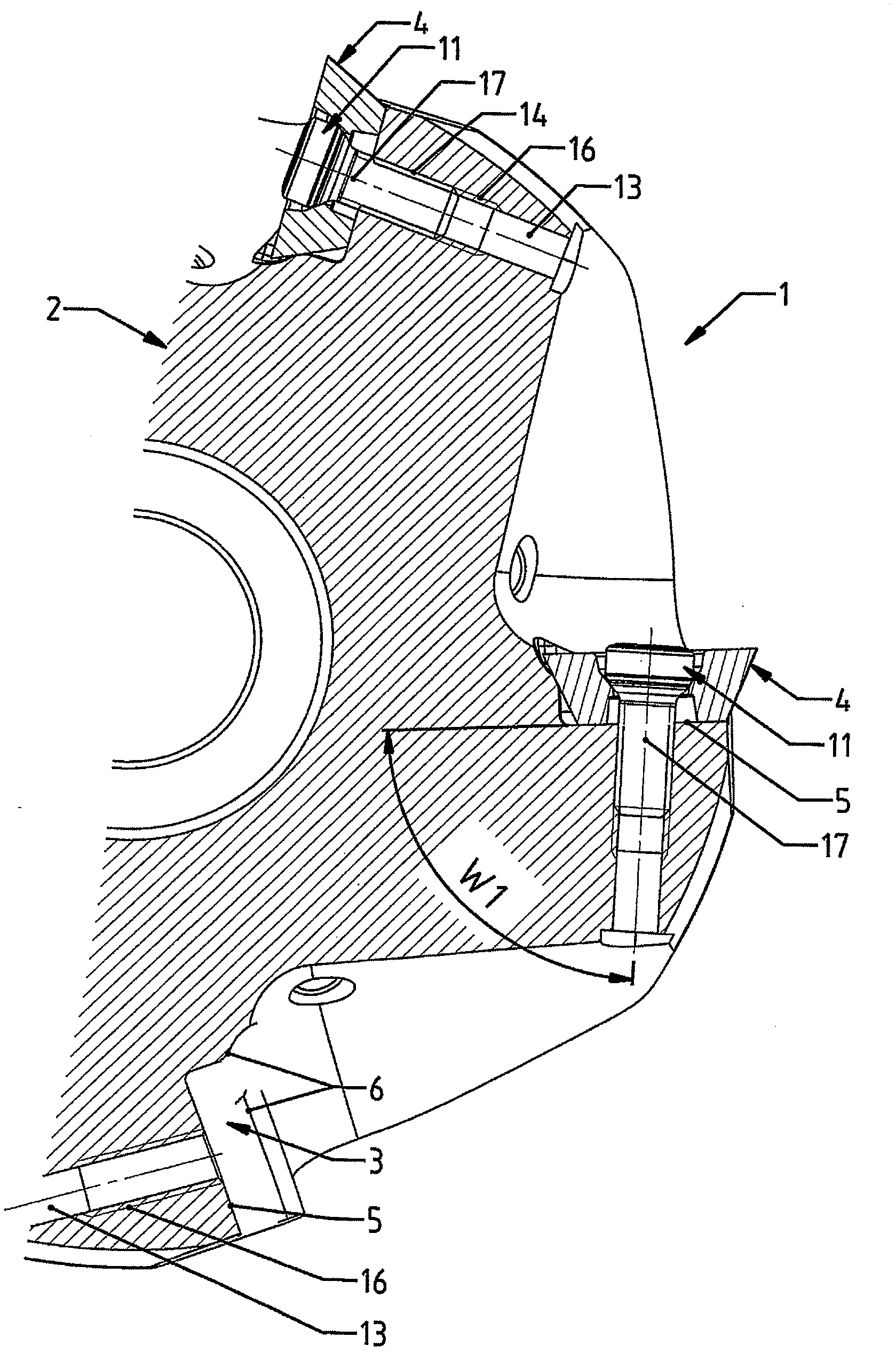
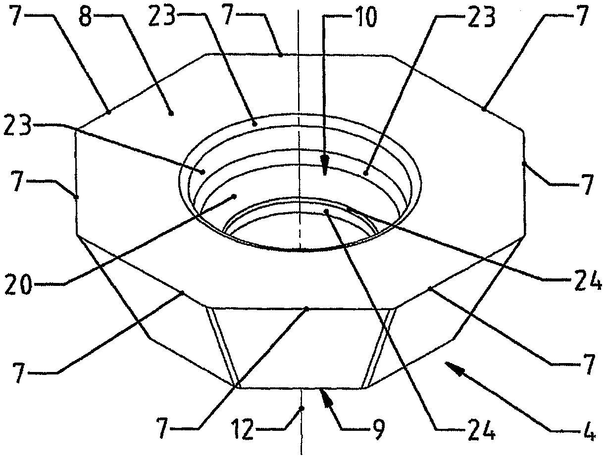
[0030] figure 1 The cutting tool 1 shown is a tool for milling which comprises a tool body 2 . The head of the tool body 2 has a plurality of mounting points (Einsatzsitze) 3 for respectively fastening exchangeable cutting inserts (Schneideinsatz) 4 . The mounting position 3 has a bottom surface 5 and a lateral stop surface 6 for positioning the cutting insert 4 . The cutting insert 4 has an octagonal cross-section with corresponding eight cutting faces 7 ( figure 2 ), whereby the cutting insert 4 is multipurpose through each active cutting face 7 . The cutting insert 4 is pierced by a central through-hole 10 from a first upper surface 8 (generally the cutting face region) to a support surface 9 situated opposite the upper surface and facing the mounting position of the bottom surface 5 . The support surface 9 rests on the bottom surface 5 in the assembled position of the cutting insert 4 .

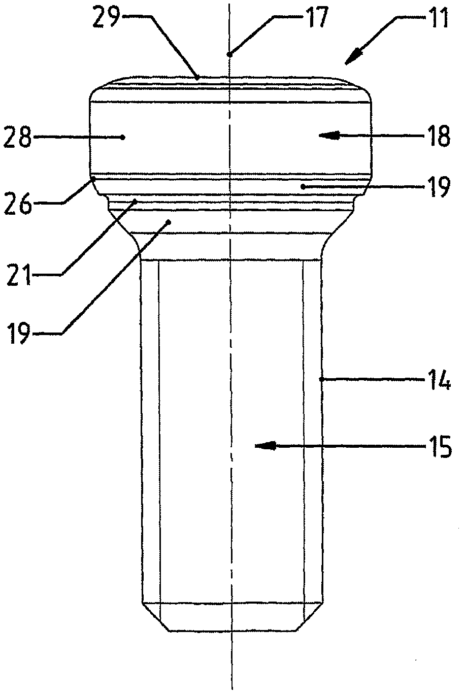
[0031] Each cutting insert 4 is fixed on the mounting location 3 by means of a l...


PUM


Abstract

The invention relates to a cutting tool (1), which comprises a main tool body (2) and at least one insert seat (3) disposed thereon, said seat having a bottom surface (5) for mounting a cutting insert (4), and further comprises a dowel pin (11), which penetrates a through-hole (10) of the mounted cutting insert (4) and the bottom surface (5) and can be fixed to the main tool body (2). A center longitudinal axis (17) of the fixed dowel pin (11) is arranged at an acute angle (W1) with respect to the bottom surface (5). The dowel pin (11) comprises a spherical segment for mounting on a bearing surface of the through-hole (10). The surface of the spherical segment is interrupted by a segment groove.

Description

technical field [0001] The invention relates to a cutting tool having the technical features of the general concept of claim 1 . Background technique [0002] Document EP 1 197 281 A discloses a cutting tool of the above-mentioned type. This known cutting tool is formed as a milling tool, the tool body of which has a plurality of mounting locations for the positioning of the individual helical cutting inserts. Each helical cutting insert is held in place by a locking pin, which is formed as a clamping screw. In this case, the clamping screw is passed through the through-opening of the helical cutting insert and screwed into a fastening hole in the tool body, wherein the fastening hole runs obliquely to the plane of the bottom surface of the mounting point. The hole wall of the through hole has a locating surface on which the locking pin or the spherical segment-shaped section of the pin head (formed as a screw head) of the clamping screw is fastened. The positioning of th...

Claims


Application Information

Patent Timeline
Patent Type & Authority Applications(China)
IPC IPC(8): B23B27/16B23C5/22
CPCB23B2205/045B23C2240/24B23B27/1662B23C2210/165B23C2200/361B23C5/2208B23B2205/04Y10T407/2274Y10T407/1936Y10T407/2276Y10T407/2278
Inventor 彼得·布尔特舍尔安东·迪波尔德乌韦·施莱因科弗
Owner CERATIZIT AUSTRIA GES
Why Eureka
Try Eureka