
Light assembly

A technology for lamp assemblies and lighting assemblies, which is applied to optical components, vehicle parts, and parts of lighting devices, etc., and can solve the problems of difficulty in uniform illumination and inability to redirect light.

Active Publication Date: 2012-05-16
3M INNOVATIVE PROPERTIES CO
View PDF23 Cites 9 Cited by
  • Summary
  • Abstract
  • Description
  • Claims
  • Application Information

AI Technical Summary

Problems solved by technology

[0007] Another drawback of the existing technology is its inability to redirect light around corners
For example, if the directional area light is in the shape of a "U" or "7", the existing technology will have difficulty illuminating the entire light evenly

Method used


Image

  • Light assembly
  • Light assembly
  • Light assembly

Examples


example 1

[0299] Microstructured (cube corner) polycarbonate films comprising PG cube corner elements were prepared using an extrusion process through a die made from multiple generations of replicas of a preferred geometry (PG) cube formed on a thin layer. Production of microstructured films using extrusion processes through microstructured tools is known in the art and generally described in U.S. Patent No. 5,450,235 (Smith et al.) and U.S. Patent No. 7,364,421 (Erickson et al.), which The disclosure is incorporated herein by reference. The mold used in this example is generally described in US Patent No. 7,329,012 (Smith), and its detailed construction is as follows. Use forward-sloping cubes such as those shown in Figure 11 of US Patent No. 7,329,012 (Smith). The forward-sloping PG cubes were formed on thin layers at a thickness of 0.173 mm (0.0068 inches). The spacing between the side slots is 0.104 mm (0.00408 inches). The angle of the side grooves is nominally 90 degrees, the ...

example 2

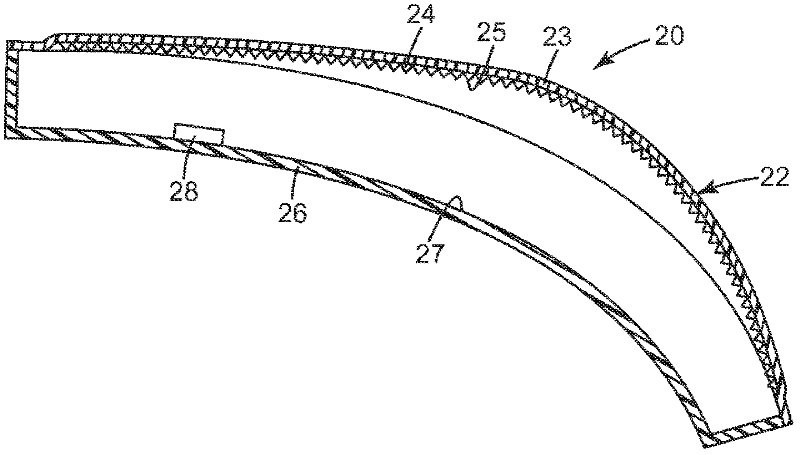
[0305] Example 2 was prepared as described in Example 1, except that the light-emitting diodes were in the sidewalls, as image 3 shown.


PUM

PropertyMeasurementUnit
Radiusaaaaaaaaaa

Abstract

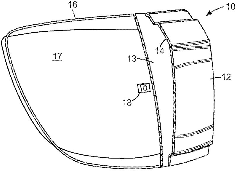
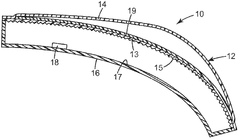
A light assembly (10) has a reflector (16), a light source(18), an outer light cover(12), and a curved transflective surface(15). Embodiments of light assemblies described herein are useful, for example, as signs, backlights, displays, task lighting, luminaire, and vehicle (e.g., cars, trucks, airplanes, etc.) components. Vehicle comprising light assemblies include those where the light assembly is a vehicle tail light assembly.

Description

Background technique [0001] Light source applications are well known in the art and include those configured to emit light relatively uniformly over a given area in a given desired direction. The degree of uniformity and aiming is application specific, but the emission area is usually comparable to the device being illuminated. [0002] Common lighting applications include backlighting for displays and signs as well as automotive lights. Liquid crystal displays (LCDs) are commonly used in laptop computers, monitors and televisions. Since liquid crystals do not generate light themselves, but only modulate it, it is common practice to provide directional area lighting behind the LCD, called a backlight. This backlight is approximately the same size as the LCD and provides a beam of light directed through the LCD toward the viewer. One type of backlight often includes at least one fluorescent lamp illuminating the edges of the plastic light guide. Light is extracted from the ...

Claims


Application Information

Patent Timeline
IPC IPC(8): F21S8/10F21V5/00F21V7/00F21Y101/00
CPCF21V23/0442F21S48/23G02B5/124F21S48/2212G02B6/001F21S48/2225F21S48/24F21S48/215F21S43/14F21S43/26F21S43/235F21S43/30F21S43/40
Inventor 史蒂芬·K·埃克哈特巴里·S·卡蓬特戴维·A·恩代尔大卫·J·伦丁马克·E·纳皮耶腊拉珍妮弗·J·萨林大卫·F·斯拉玛卡尔·A·维克约翰·A·惠特利
Owner 3M INNOVATIVE PROPERTIES CO
Learn More