Al technical title is built by PatSnap Al team. It summarizes the technical point description of the patent document.
An edge-rolling and reeling technology, which is applied in the field of coiling waste edges of a thick plate production line, can solve the problems of easy jamming, easy jamming of the pushing device, and difficulty in unloading.
Inactive Publication Date: 2012-05-23
BEIJING STAR RIVER INTEGRATED EQUIP TECH
View PDF0 Cites 7 Cited by
Summary
Abstract
Description
Claims
Application Information
AI Technical Summary
This helps you quickly interpret patents by identifying the three key elements:
Problems solved by technology
Method used
Benefits of technology
Problems solved by technology
[0003] In order to overcome the difficulty of unloading in the waste edge coiling in the prior art, and the phenomenon that the pushing device is easy to be stuck, the present inven
Method used
Image
Click on the blue label to locate the original text in one second.
Reading with bidirectional positioning of images and text.
Examples
Embodiment Construction
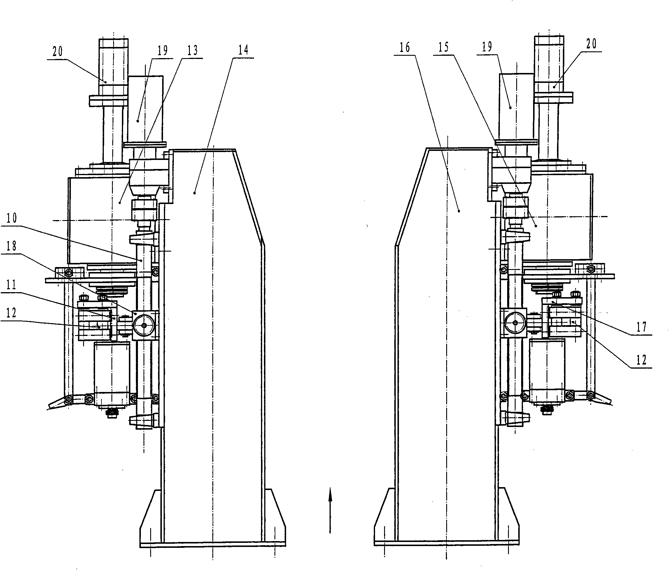
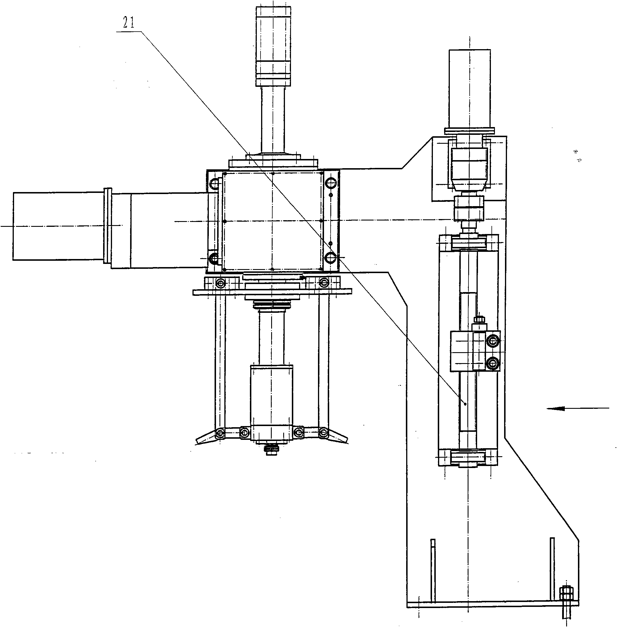
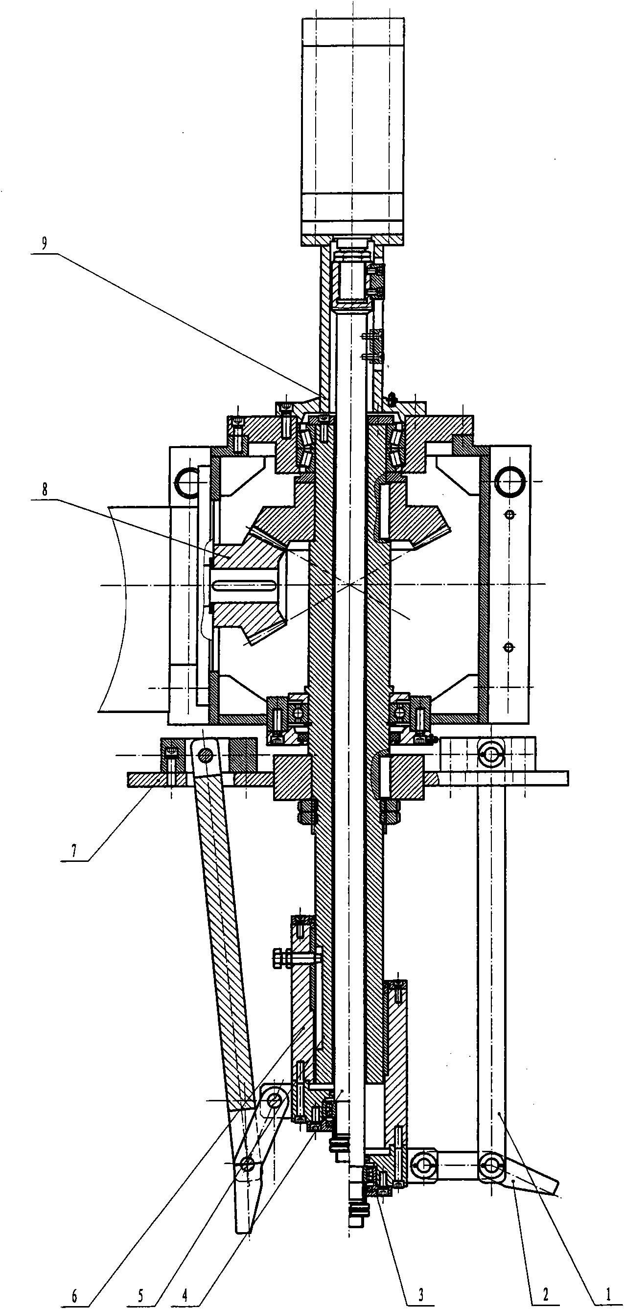
[0015] as attached Figure 1-3 As shown, on both sides of the production line, a waste edge coiler is respectively installed, and the waste edge passes through the guide wheel 12 of the guide mechanism, and is wound on the vertical pole 1 of the coiler, and the transmission mechanism 8 driven by the motor 19 drives the guide The screw mandrel 21 of the mechanism, the screw mandrel 21 rotates and drives the slider 18 worn on the top to slide along the guide bar 10, the left bracket 11, the right bracket 17 are installed on the slider 18, and the guide wheel 12 is fixed on the left and right brackets for reciprocating motion. The waste edge passes through the middle of the guide wheel, and the reciprocating motion of the slider 18 drives the guide wheel 12 on the left and right brackets to move, bringing the waste edge to reciprocate. , under the action of power, the reel rotates, and the waste edge is wound with the rotation of the reel. When it is wound into a ball of a certai...
PUM
Abstract
The invention provides a scrap edge coiler device. One scrap edge coiler is arranged on each of two sides of the rear side of a circle shear on a production line. The device comprises the two scrap edge coilers which are symmetrically arranged on the left and right sides of the production line; each scrap edge coiler consists of a left frame (14), a right frame (16), a left gear box (13), a right gear box (15), a motor (18), a transmission mechanism (8) and a drum; the left gear box (13) is fixed on the left frame (14); the right gear box (15) is fixed on the right frame (16); the motor (18) drives the transmission mechanism (8) to rotate the drum; the drum is vertical; the expansion and shrinking of the drum is realized in the mode that an oil cylinder (19) drives a pull rod (4) to slide in a hollow shaft (5); the lower end of the pull rod (4) is fixed with a sliding sleeve (6); and the sliding sleeve (6) is connected with a rotating claw to expand and shrink. By using the scrap edge coiler device, materials can be conveniently unloaded, labor time is saved, production efficiency is improved, and the production line can operate easily and smoothly.
Description
Technical field: [0001] The invention belongs to the collection equipment of narrow strips, in particular to the coiling of the waste edge of the thick plate production line. Background technique: [0002] Waste edge coiling equipment in the prior art is generally horizontal, as attached Figure 3-5 As shown in, the overall equipment consists of 22, roller device, 23, coiling device, 24, guiding device, 25, pushing device, 26, frame, 27, motor, 28, reducer, 29, transmission parts, 30 , the baffle plate, the motor 27 drives the reducer 28 to drive the coiling device 23 through the transmission part 29, the coiling device 23 is horizontal, the steel plate after cutting off the waste edge is transferred to the subsequent process step through the idler device 22, and the waste The side coiling device 23 rotates to drive the waste side wound on the upper side, and the motor 27 passes through the reducer 28 through a remote transmission, and drives the guiding device to reciprocat...
Claims
Application Information
Patent Timeline
Application Date:The date an application was filed.
Publication Date:The date a patent or application was officially published.
First Publication Date:The earliest publication date of a patent with the same application number.
Issue Date:Publication date of the patent grant document.
PCT Entry Date:The Entry date of PCT National Phase.
Estimated Expiry Date:The statutory expiry date of a patent right according to the Patent Law, and it is the longest term of protection that the patent right can achieve without the termination of the patent right due to other reasons(Term extension factor has been taken into account ).
Invalid Date:Actual expiry date is based on effective date or publication date of legal transaction data of invalid patent.