Surface lighting apparatus
A surface lighting and surface light source technology, applied in lighting devices, lighting device parts, lighting and heating equipment, etc., can solve the problems of decreased light utilization efficiency, increased component cost, uneven brightness, etc.
- Summary
- Abstract
- Description
- Claims
- Application Information
AI Technical Summary
Problems solved by technology
Method used
Image
Examples
no. 1 approach
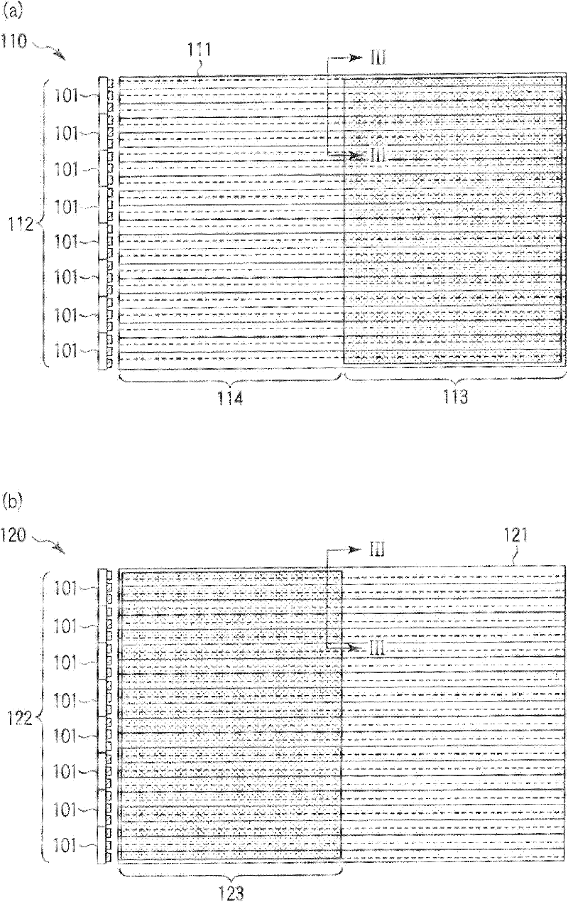
[0031] figure 1 The surface lighting device according to the first embodiment is schematically shown. The surface lighting device such as figure 1 As shown, with multiple (in figure 1 In the figure is a structure in which two) surface light source units 110, 120 are stacked. The surface light source units 110 and 120 respectively include light guide plates 111 and 121 and linear light sources 112 and 122 . The light guide plates 111 and 121 and the linear light sources 112 and 122 are supported and fixed by a frame-shaped casing not shown in the figure.
[0032] The light guide plates 111 and 121 are made of a light-transmitting material and formed in a thin plate shape. As a material of the light guide plates 111 and 121, resin materials such as acrylic resin and polycarbonate resin can be used, for example.
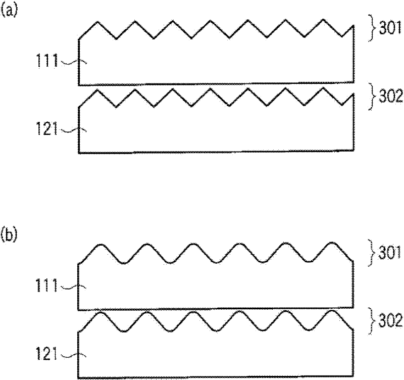
[0033] The light guide plates 111 and 112 respectively have a front surface, a back surface, and four side surfaces. The front surface and the back surface are su...
no. 2 approach
[0069] Figure 10 A surface lighting device according to the second embodiment is schematically shown. This surface lighting device has a structure in which a surface light source unit 110 and a surface light source unit 1020 are stacked. The surface light source unit 110 includes a light guide plate 111 and a linear light source 112 disposed opposite to the side surface of the light guide plate 111. The surface light source unit 1020 includes The light guide plate 1021 and the linear light source 122 disposed opposite to the side surface of the light guide plate 1021 . exist figure 1 surface lighting and Figure 10 In the surface lighting device, the shape of the light guide plate of the surface light source unit in the lower layer is different.
[0070] In the first embodiment, the upper light guide plate 111 and the lower light guide plate 121 have the same size, but in the second embodiment, the lower light guide plate 1021 is smaller in size than the upper light guide ...
no. 3 approach
[0076] Figure 12 A surface lighting device according to the third embodiment is schematically shown. The third embodiment has the figure 1 The surface illuminating device according to the first embodiment shown is arranged bilaterally symmetrically, and has a structure in which left and right light guide plates are integrated. Here, the left-right direction refers to the light emission direction of the linear light source.
[0077] Figure 12 The surface lighting device has a structure in which a surface light source unit 1210 and a surface light source unit 1220 are stacked. The surface light source unit 1210 includes a light guide plate 1211 and a pair of linear light sources 112a and 112b , the surface light source unit 1220 includes a light guide plate 1221 and linear light sources 122a and 122b disposed opposite to a pair of side surfaces of the light guide plate 1221 facing each other.
[0078] Figure 13 (a) and Figure 13 (b) Separately shows the surface light s...
PUM
 Abstract
Description
Claims
Application Information
 - R&D
- Intellectual Property
- Life Sciences
- Materials
- Tech Scout
- Unparalleled Data Quality
- Higher Quality Content
- 60% Fewer Hallucinations
Browse by: Latest US Patents, China's latest patents, Technical Efficacy Thesaurus, Application Domain, Technology Topic, Popular Technical Reports.
© 2025 PatSnap. All rights reserved.Legal|Privacy policy|Modern Slavery Act Transparency Statement|Sitemap|About US| Contact US: help@patsnap.com


