Lighting device for alignment and exposure device having the same

A technology of lighting device and control device, which is applied in the direction of photographic plate-making process exposure device, micro-lithography exposure equipment, patterned surface photo-plate-making process, etc., and can solve the problems of accurate imaging and inability to align mark imaging, etc.

Active Publication Date: 2012-05-23
ADTEC ENG
View PDF8 Cites 3 Cited by
  • Summary
  • Abstract
  • Description
  • Claims
  • Application Information

AI Technical Summary

Problems solved by technology

[0006] The alignment marks made by the laser hole forming device on the board are slightly different from the surface of the board, and the alignment marks cannot be imaged with sufficient accuracy
In addition, other conditions of the board vary due to the "multi-variety low-volume production", which is one of the reasons why it is difficult to accurately photograph the alignment marks

Method used


Image

  • Lighting device for alignment and exposure device having the same
  • Lighting device for alignment and exposure device having the same
  • Lighting device for alignment and exposure device having the same

Examples


Embodiment Construction

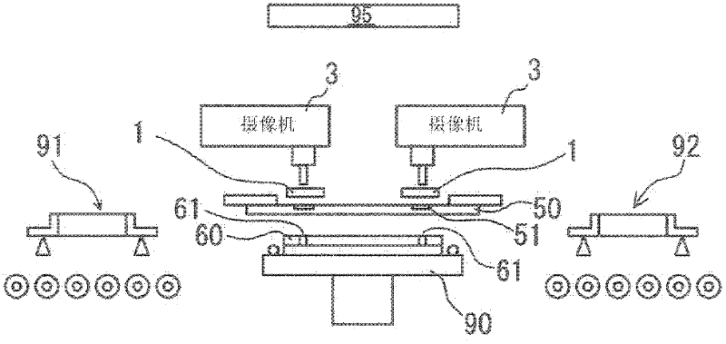
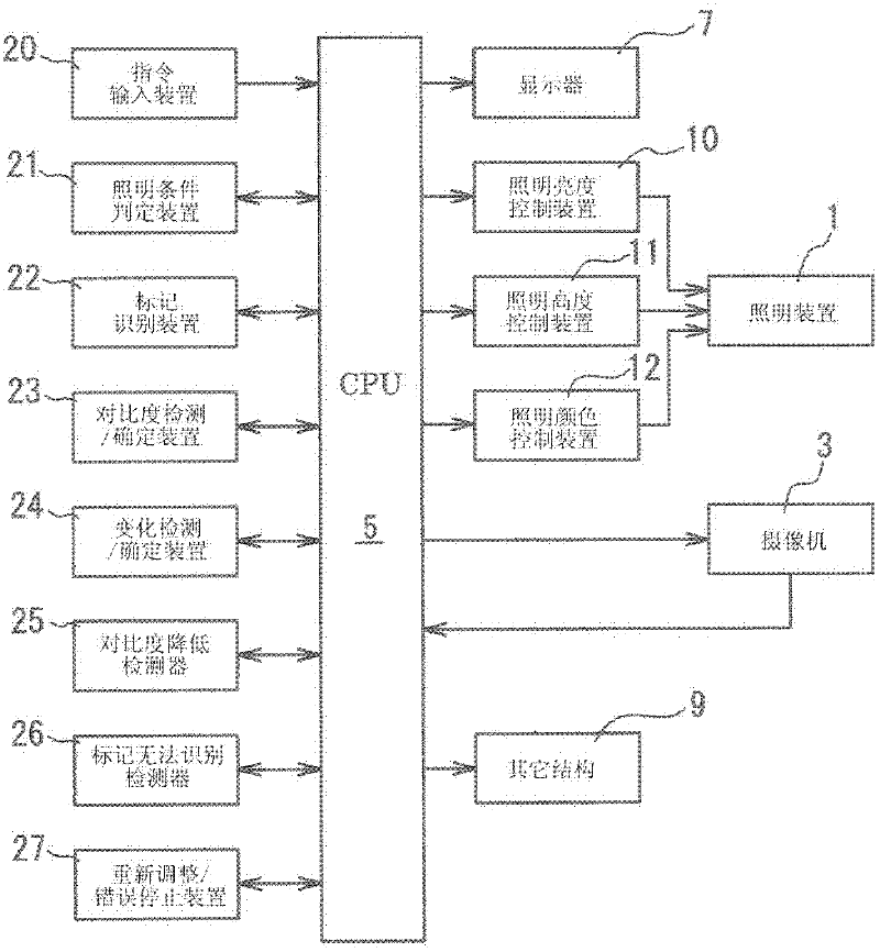
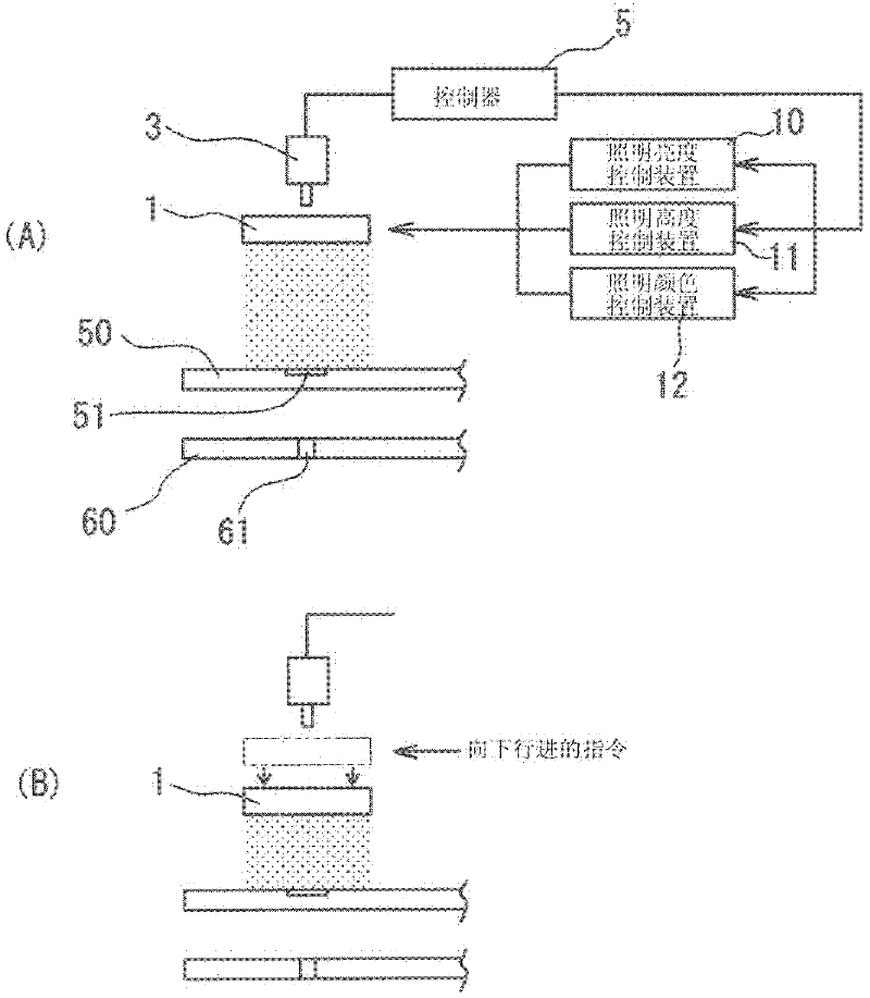
[0027] Hereinafter, the present invention will be described in detail with reference to the accompanying drawings. figure 1 An overview of an exposure apparatus used to manufacture printed circuit boards is shown. figure 2 shows the block diagram, while image 3 Details of the lighting device 1 are shown.

[0028] The pattern drawn on the mask 50 is used by the light source 95 to expose the printed circuit board 60 carried on the exposure table 90 by the loading device 91, and then the printed circuit board 60 is transferred to the next process by the carrying device 92. .

[0029] Four CCD cameras 3 are disposed above the mask 50 at positions corresponding to the four corners of the printed circuit board 60 . Before exposure, alignment between the mask 50 and the printed circuit board 60 is performed using the mask marks 51 drawn on the corners of the mask 50 and the board marks 61 formed on the corners of the printed circuit board 60. allow. The exposure stage 90 can m...


PUM


Abstract

A ring shape lighting device (1), used for lighting the mark around a CCD camera (3), has a lighting device (1), a lighting brightness control device (10), a lighting height control device (11), a lighting color control device (12) and a controller (5). The controller controls these devices and detects the marks using the CCD camera (3), by changing the lighting brightness at 1 percent step from 1 to 100 percent with different combinations of lighting height and lighting color. The device detects the mark contrasts using a contrast detection / determination device (23) and detects the variance using a variance detection / determination device (24). The device then determines the best lighting condition based on the variance.

Description

technical field [0001] The invention relates to an illumination device for alignment and an exposure device having the same. Background technique [0002] Photolithography has been applied to the manufacture of printed circuit boards, in which a predetermined pattern is photolithographically printed by an exposure device on the surface of a substrate coated with a photosensitive material such as photoresist, and thereafter the pattern is formed on the substrate by an etching process. pattern. [0003] At the time of exposure by an exposure device, it is generally necessary to align the photomask and the circuit board by using image detection devices such as a CCD camera for imaging and lighting devices. [0004] The pattern of printed circuit boards has become miniaturized, and laser drilling that can make micro-holes has been adopted, so the laser hole-forming device for forming micro-holes is now commonly used to manufacture alignment marks on printed circuit boards. [...

Claims


Application Information

Patent Timeline
Patent Type & Authority Applications(China)
IPC IPC(8): G03F7/20G03F9/00
CPCG03F9/7069H05K3/0008H05K2201/09918G03F9/7046G03F9/00G03F7/091G03F7/70141G03F7/70483G03F7/70775G03F7/70833
Inventor 种村次记中岛裕名古屋淳大矢佳幸
Owner ADTEC ENG
Why Eureka
Try Eureka