Ejection mechanism, pull-out guide and ejection system
What is AI technical title?
AI technical title is built by Patsnap AI team. It summarizes the technical point description of the patent document.
A technology of pushing out mechanism and guiding device, which is applied to the suspension device of wing sash, building structure, door/window accessories, etc., can solve problems such as damage, and achieve the effect of simplifying operation and reducing the number of
Active Publication Date: 2012-05-23
PAUL HETTICH
View PDF6 Cites 19 Cited by
Summary
Abstract
Description
Claims
Application Information
AI Technical Summary
This helps you quickly interpret patents by identifying the three key elements:
Problems solved by technology
Method used
Benefits of technology
Problems solved by technology
The disadvantage of this device for opening and locking is that the locking mechanism can only be unlocked by pressing the drawer
In addition, the locking is achieved by a number of parts, which can only withstand limited mechanical loads, since they are small in size and can be damaged
Method used
Image
Click on the blue label to locate the original text in one second.
Reading with bidirectional positioning of images and text.
Examples
Embodiment Construction
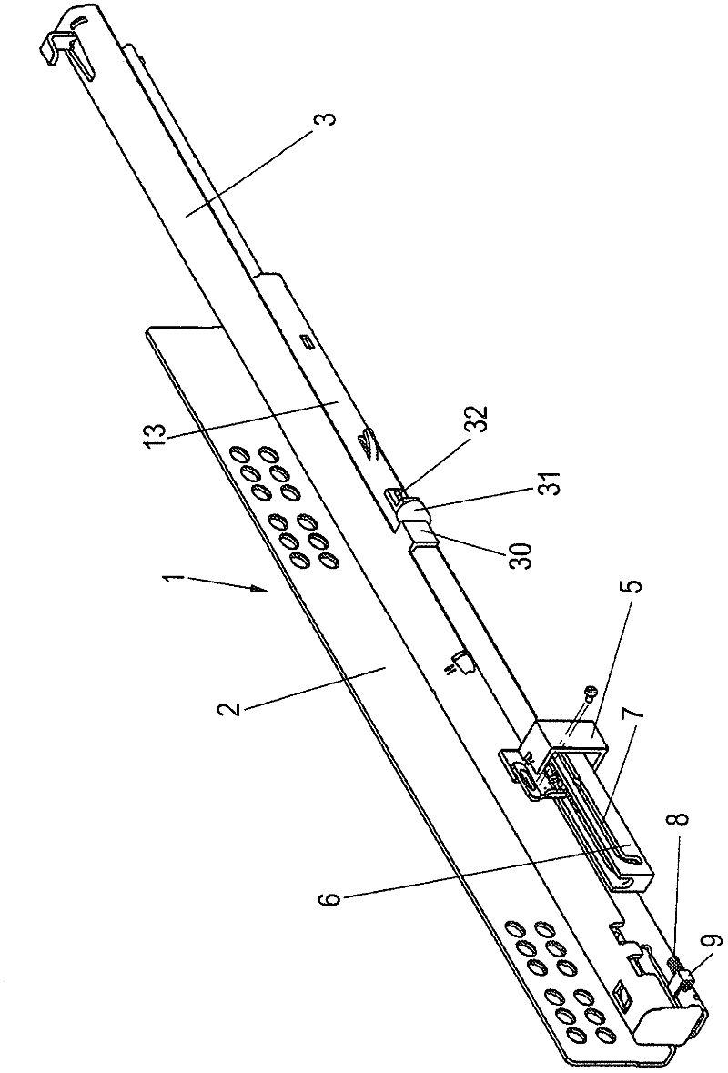
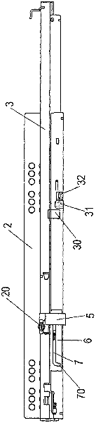
[0046] The push-out mechanism according to the invention is mounted on a pull-out guide 1 having a guide rail 2 and a movable slide rail 3 which can be mounted on the furniture body. If necessary, there is an intermediate rail extending the pull-out between the guide rail and the sliding rail, so that it can be pulled out completely. It is also possible to fit the ejection mechanism on pivotable furniture doors or other movable furniture parts.
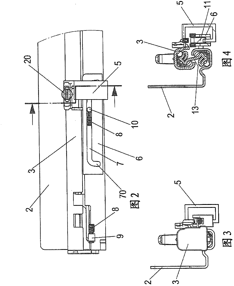
[0047] Said ejection mechanism comprises an actuator 5 fixed on a slide rail 3 , which is arranged in a locked position on a housing 6 with curved guides 7 . A driver 11 is guided in the curve guide 7 and is pretensioned in the opening direction by an energy store 8 designed as a tension spring. The energy store 8 is held at one end on a holder 9 fastened to the guide rail 2 and at the opposite side on a carrier 11 .
[0048] In the locked position, a web 30 arranged on the slide rail bears against a resilient stop 31 , which is des...
PUM
Abstract
An ejection mechanism, particularly for mobile pieces of furniture, comprising a curve guide (7, 7', 7'', 7''', 7''''), along which a driver (11, 11', 11'', 11''', 11'''') can be displaced, wherein the driver (11, 11', 11'', 11''', 11'''') is prestressed in one direction by at least one force accumulator (8, 8') and can be latched in a locked position at the curve guide (7, 7', 7'', 7''', 7'''') with the stressed force accumulator (8, 8'), and an activator (5, 5', 5'', 5''', 5''''), which can be coupled to the driver (11, 11', 11'', 11''', 11'''') at least in the locked position, wherein the activator (5, 5'', 5''', 5'''') can be moved relative to the curve guide (7, 7'', 7''', 7'''') or the curve guide (7') can be moved relative to the activator (5'), wherein in the locked position the driver (11, 11', 11'', 11''', 11'''') can be released by a relative movement of the activator (5, 5'', 5''', 5''''); relative to the curve guide (7, 7'', 7''', 7'''') or by a relative movement of the curve guide (7') relative to the activator (5'). The activator (5, 5', 5'', 5''', 5'''') and / or the curve guide (7, 7', 7'', 7''', 7'''') can be moved both in a first direction and in an opposite second direction to release the driver (11, 11', 11'', 11''', 11'''').
Description
technical field [0001] The invention relates to an ejection mechanism, in particular for movable furniture parts, which has a curved guide along which a driver can be displaced, wherein the driver is pretensioned in one direction by at least one energy store , and can be locked in the locked position by means of a tensioned accumulator on the curve guide, the push-out mechanism also has an actuator that can be coupled with the driver at least in the locked position, wherein the actuator can be relative to the curve The guiding device moves, or the curved guiding device can move relative to the actuator, wherein in the locked position, the entrainer is activated by the relative movement of the actuator relative to the curved guiding device or by the relative movement of the curved guiding device relative to the actuator. unlockable; the invention also relates to a pull-out guide and an ejection system. Background technique [0002] EP 1 845 821 discloses a device for opening...
Claims
Application Information
Patent Timeline
Application Date:The date an application was filed.
Publication Date:The date a patent or application was officially published.
First Publication Date:The earliest publication date of a patent with the same application number.
Issue Date:Publication date of the patent grant document.
PCT Entry Date:The Entry date of PCT National Phase.
Estimated Expiry Date:The statutory expiry date of a patent right according to the Patent Law, and it is the longest term of protection that the patent right can achieve without the termination of the patent right due to other reasons(Term extension factor has been taken into account ).
Invalid Date:Actual expiry date is based on effective date or publication date of legal transaction data of invalid patent.

