Machine tool having a protective cover

A technology of machine tools and protective covers, which is applied in the direction of manufacturing tools, metal processing equipment, grinding machines, etc., can solve the problems of difficult implementation of the integral representation of clamping hoops and protective covers, and the cover body exceeds the reliable angle range. Effect of small rupture risk

Active Publication Date: 2012-05-23
ROBERT BOSCH GMBH
View PDF6 Cites 7 Cited by
  • Summary
  • Abstract
  • Description
  • Claims
  • Application Information

AI Technical Summary

Problems solved by technology

[0003] The one-piece clamping band and boot represent a more laborious implementation
Furthermore, this embodiment is not suitable for reliably limiting the rotation of the protective hood to the maximum permissible angular value in the event of disc cutter breakage
Due to the relatively high mass of the protective hood, there is a risk that the hood will rotate sufficiently beyond the reliable angular range due to inertial forces despite the stop being achieved on the clamping collar by the stop device

Method used


Image

  • Machine tool having a protective cover
  • Machine tool having a protective cover
  • Machine tool having a protective cover

Examples


Embodiment Construction

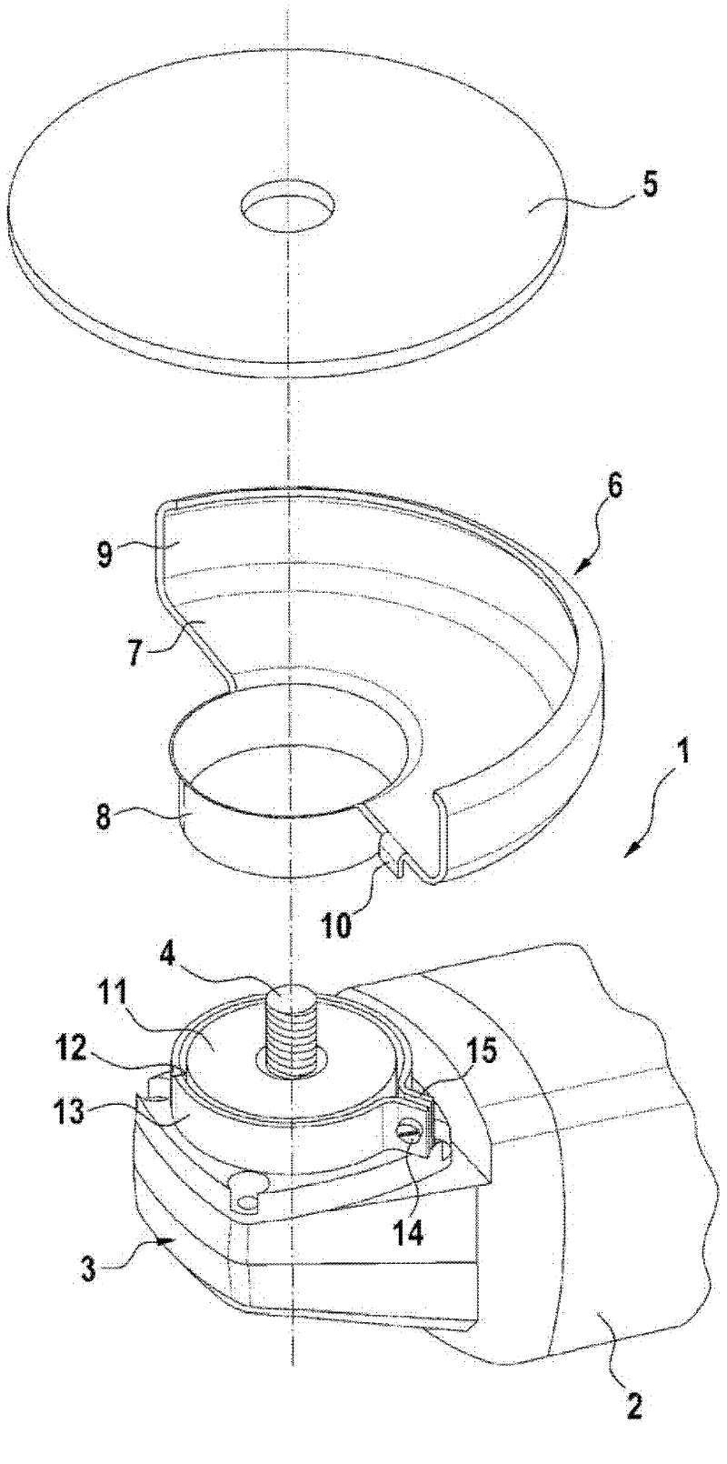
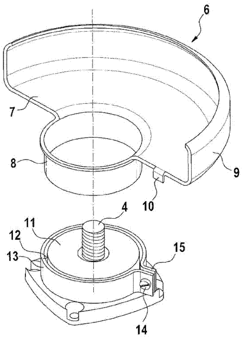
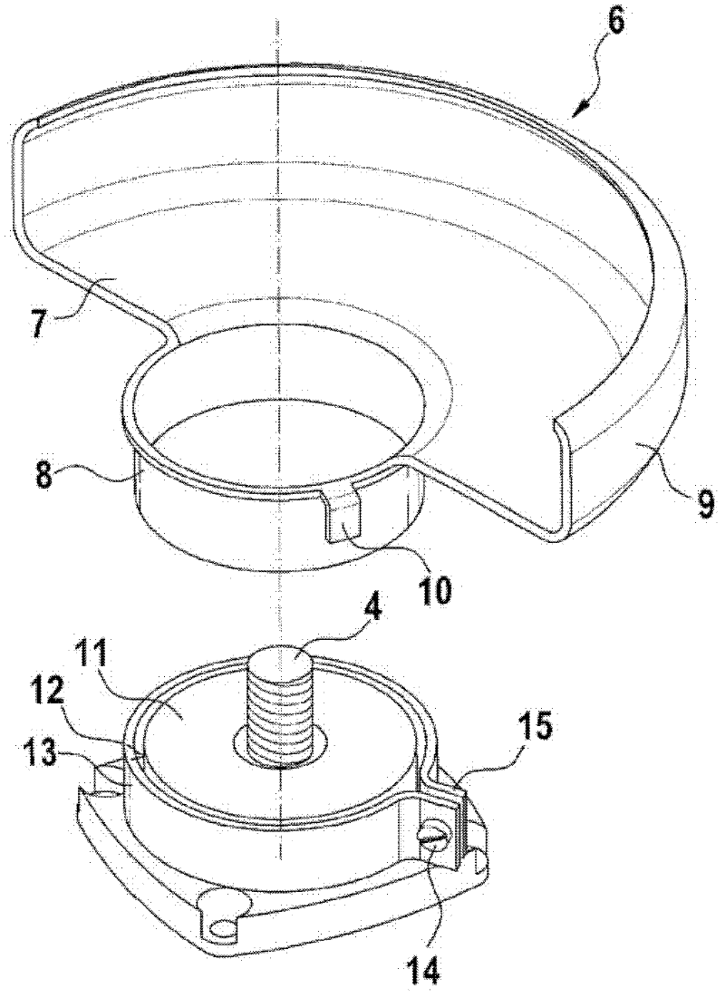
[0031] in figure 1 The hand-held machine tool 1 shown in the figure refers to an angle grinder with an electric drive motor in a housing 2, wherein the drive movement of the electric drive motor is transmitted to the driven shaft 4 perpendicular to the motor shaft through the transmission device 3 Above, the grinding disc 5 constituting the tool can be detachably connected with the driven shaft. The hand-held power tool 1 has a protective cover 6, which includes an at least approximately semicircular cover 7, a clamping flange 8 and a surrounding edge area 9 on the cover 7, which is approximately in the assembled position. Parallel to the grinding disc 5. The cover body 7, the clamping flange 8 and the edge region 9 are formed in one piece. The protective cover 6 is detachably connected to the hand-held power tool 1 via a clamping flange 8.

[0032] An angular (curved) stop element 10 is integrally formed in the area of ​​the end edges of the cover body 7, which stop element is...


PUM


Abstract

The invention relates to a machine tool comprising a protective cover having a clamping joint that can be attached in a flange on the machine by means of a clamping device. A stop device is provided for limiting the relative rotary motion between the protective cover and the flange.

Description

Technical field [0001] The invention relates to a machine tool, in particular an angle grinder, with a protective cover covering the tool according to the preamble of claim 1. Background technique [0002] WO 2009 / 054275 A1 discloses a machine tool with a rotary tool in the form of a grinding disc, which is covered (overlapped) by a protective cover which is fixed on a flange on the machine side. The protective cover has a clamping flange, which can be placed on the flange and fixed to the flange by means of a clamping band. The protective cover can be fixed on the flange in different angular positions. In order to change the angular position, the clamping band is loosened and the protective cover can then be swung into the desired angular position. The swing range is limited to a certain angle range; for this, a stop device is provided on the machine tool, which includes a protrusion on the clamping band and a counterpart on the machine tool housing. The clamping band and the...

Claims


Application Information

Patent Timeline
Patent Type & Authority Applications(China)
IPC IPC(8): B24B23/02B24B55/05
CPCB24B23/028B24B55/052
Inventor F·埃森魏因
Owner ROBERT BOSCH GMBH
Why Eureka
Try Eureka