Vertical drilling machine

A drilling machine and vertical technology, applied in the direction of stone processing tools, working accessories, manufacturing tools, etc., can solve the problems of damaging drilling equipment and glass, reducing the guiding accuracy of guide rails, and inaccurate docking of glass, so as to reduce the amount of wear , improve production efficiency, and avoid the effect of position deviation

Pending Publication Date: 2020-01-17
合肥明皓玻璃装饰有限公司
View PDF0 Cites 6 Cited by
  • Summary
  • Abstract
  • Description
  • Claims
  • Application Information

AI Technical Summary

Problems solved by technology

[0003] In the existing vertical glass drilling machine, the angle between the glass feeding and discharging conveyor belt and the ground is less than 90 degrees, the drilling device is set on the drilling feeding platform, and the drilling feeding platform is vertically attached to the On the frame, and move back and forth on the frame, because the drilling device is suspended on the feed platform and controlled forward or backward by the feed platform, the drilling device and the drilling platform form a cantilever beam structure on the frame, In turn, the guide rails are severely worn and the guiding accuracy of the guide rails is reduced. After long-term use, it will cause the vertical and horizontal displacement of the drilling device, resulting in a reduction in drilling accuracy. In severe cases, it may cause drilling failure, damage to drilling equipment and Glass
[0004] Moreover, in the process of glass feeding, only a single position detection device is arranged or the stop position of the glass is controlled only by the rotation of the feeding conveyor belt, which leads to inaccurate stop of the glass and low precision of punching the glass

Method used


Image

  • Vertical drilling machine
  • Vertical drilling machine
  • Vertical drilling machine

Examples


Embodiment Construction

[0033] The technical solutions in the embodiments of the present invention will be clearly and completely described below in conjunction with the accompanying drawings in the embodiments of the present invention. Obviously, the described embodiments are only a part of the embodiments of the present invention, rather than all the embodiments. Based on the embodiments of the present invention, all other embodiments obtained by those of ordinary skill in the art without creative work shall fall within the protection scope of the present invention.

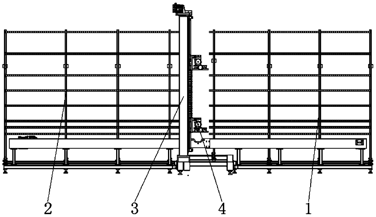
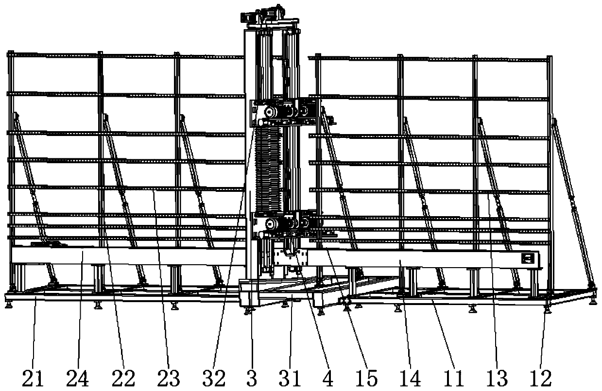
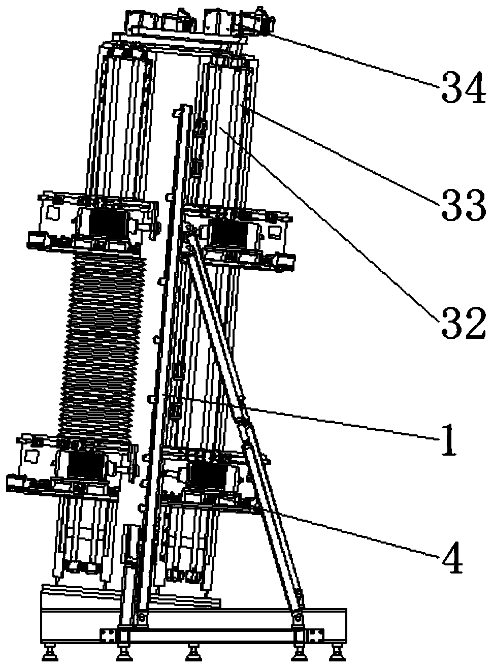
[0034] See Figure 1-4 In the embodiment of the present invention, a vertical punching machine includes a glass feed rack 1, a column 3, and a glass discharge rack 2 arranged in sequence. The column 3 is provided with a drilling portion 4, and the glass feed rack 1, The column 3 and the glass discharging rack 2 are located in the same plane.

[0035] The glass feeder 1 includes a feeder base 11, the upper end of the feeder base 11 is rota...


PUM


Abstract

The invention discloses a vertical drilling machine comprising a glass feeding frame, a stand column and a glass discharging frame which are arranged in sequence. A drilling part is arranged on the stand column, the drilling part is connected to the stand column in a sliding manner, the drilling part comprises two sets of drilling platforms which are symmetrically arranged, each drilling platformcomprises a supporting plate which is connected with the stand column in a sliding manner up and down and is vertically arranged, the sides, away from the stand column, of the supporting plates are fixedly connected with a supporting platform, the supporting platform is perpendicular to the supporting plates, and the supporting plates are perpendicular to the glass feeding frame. A drilling motoris connected to the upper end of the supporting platform in a sliding manner. Since the glass feeding frame is arranged, two position detection devices are arranged on the glass feeding frame, and therefore glass drilling precision is improved. The reliability of the drilling platform is improved, wear amount of a guide rail is reduced, the deviation of the position of the drilling motor caused byexcessive wear of one side of the guide rail is avoided, and the drilling precision and the stability of the drilling platform are improved.

Description

Technical field [0001] The invention relates to the technical field of glass punching equipment, in particular to a vertical punching machine. Background technique [0002] Glass drilling machine is a machine specially used for glass drilling, discrete glass drilling machine and horizontal glass drilling machine. The vertical glass drilling machine is automatically controlled by PLC. During operation, you only need to put the glass on the conveyor belt, input the drilling position data, start the button, and drill all the holes after automatic positioning, and automatically stop after finishing the work, with high drilling efficiency , The hole position is accurate, suitable for the processing of architectural glass and furniture glass; [0003] In the existing vertical glass drilling machine, the glass feeding and discharging conveyor belts are arranged at an angle of less than ninety degrees with the ground. The drilling device is arranged on the drilling feeding platform, and t...

Claims


Application Information

Patent Timeline
Patent Type & Authority Applications(China)
IPC IPC(8): B28D1/14B28D7/00B28D7/04B28D7/02
CPCB28D1/14B28D7/00B28D7/02B28D7/04
Inventor 郭光明杨丽桦郭哲郭奕潼曹晟铭朱跃跃张胜兵
Owner 合肥明皓玻璃装饰有限公司
Why Eureka
Try Eureka