Robot With Fixing Device

A technology for fixing devices and robots, which is applied in the directions of robots, manipulators, mechanical equipment, etc., and can solve problems such as the inability to fix arms.

Inactive Publication Date: 2015-09-02
FANUC LTD
View PDF1 Cites 8 Cited by
  • Summary
  • Abstract
  • Description
  • Claims
  • Application Information

AI Technical Summary

Problems solved by technology

However, the above-mentioned stopper needs to be installed at a predetermined position corresponding to the allowable operating angle of the arm. Therefore, even if this stopper is used, the arm cannot be fixed at any angle.

Method used


Image

  • Robot With Fixing Device
  • Robot With Fixing Device
  • Robot With Fixing Device

Examples


Embodiment Construction

[0028] Next, embodiments of the present invention will be described in detail with reference to the drawings. In the respective drawings, the same reference numerals are attached to the same components. In addition, the following description is not limited to the protection scope of the invention described in a claim, the meaning of a term, etc.

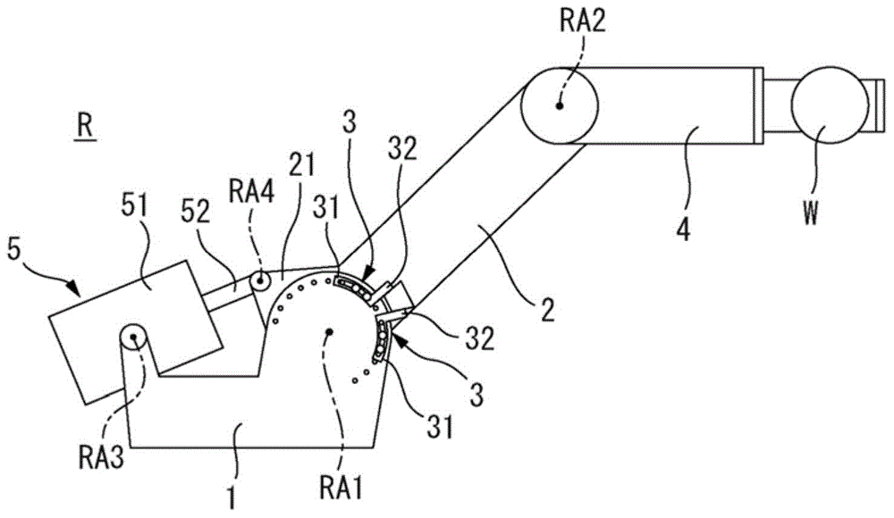
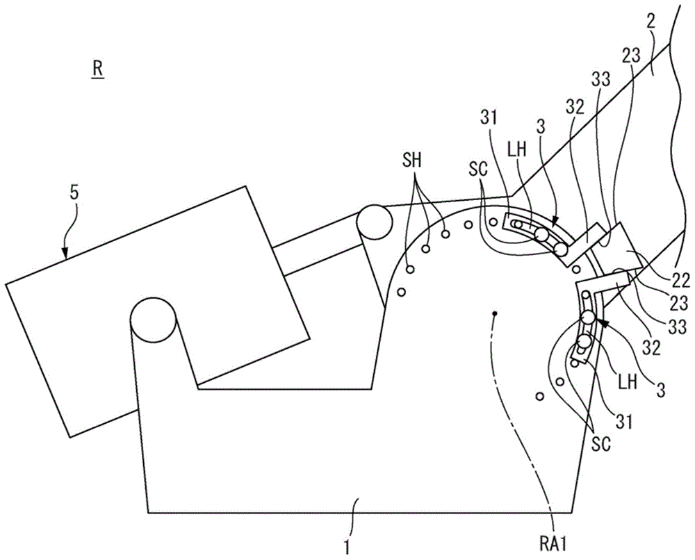
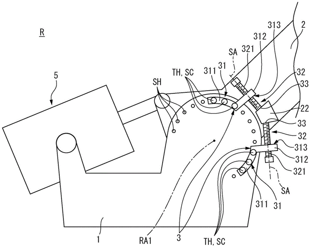
[0029] refer to figure 1 as well as figure 2 , and the robot according to the first embodiment of the present invention will be described. figure 1 It is a side view showing the appearance of the robot R exemplified in this embodiment. The robot of this embodiment is an industrial robot having an arm to which various end effectors can be attached, and includes: a first member and a second member, and the first member and the second member are relatively rotatable around a predetermined rotation axis and a fixing device, the fixing device is used to limit the relative rotational movement of the first member and the second membe...


PUM


Abstract

A robot of the present invention includes a swivel base and lower arm which are connected to be able to rotate relative to each other about a rotation axis, and a fixing device which restricts rotating motion of the swivel base and lower arm about the rotation axis. The fixing device includes a mounting part which is mounted to the swivel base, and an abutting part which extends from the mounting part and abuts against the lower arm to restrict relative rotating motion about the rotation axis. An abutting position of the abutting part with respect to the lower arm can be changed steplessly in a circumferential direction about the rotation axis.

Description

technical field [0001] The invention relates to a robot with a fixation device for limiting relative rotational movement of two components and a fixation device for limiting relative rotational movement of two components. Background technique [0002] Most vertical articulated robots have a servomotor with a built-in brake as an arm drive unit, and when the drive current of the servomotor is cut off, the brake is automatically activated to prevent the arm from falling due to gravity. On the other hand, when the servo motor is replaced due to failure or the like, it is necessary to replace the servo motor with a component that temporarily prevents the arm from falling. In this case, for example, an overhead crane that suspends the arm from above or any support base that supports the arm from below can be used. [0003] However, since the arm of the vertical articulated robot operates against gravity, various gravity balance devices using coil springs or the like are sometime...

Claims


Application Information

Patent Timeline
Patent Type & Authority Applications(China)
IPC IPC(8): B25J19/06
CPCY10S901/49B25J19/06B25J19/0004B25J17/00B25J19/0066Y10S901/28B25J9/101Y10T74/20329Y10T74/20636
Inventor 米田敬词
Owner FANUC LTD
Why Eureka
Try Eureka