Control device for the brake system of a vehicle

A technology for braking equipment and controllers, applied in the directions of brakes, antennas suitable for movable objects, vehicle components, etc., can solve problems such as expensive and high technical requirements, and reduce material costs, costs, and laying cables. The effect of consumption

Active Publication Date: 2012-05-23
ZF CV SYST EURO BV
View PDF5 Cites 8 Cited by
  • Summary
  • Abstract
  • Description
  • Claims
  • Application Information

AI Technical Summary

Problems solved by technology

However, the flexible routing of thick cable bundles without compro...

Method used


Image

  • Control device for the brake system of a vehicle
  • Control device for the brake system of a vehicle
  • Control device for the brake system of a vehicle

Examples


Embodiment Construction

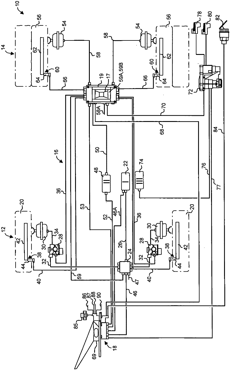
[0032] figure 1 A dual-axle vehicle 10 is shown schematically with a front axle 12 and a rear axle 14 as well as a braking system 16 . The braking system 16 has a controller by means of which the braking force can be calculated electronically and a braking force signal can be generated as a function of the calculated braking force. Furthermore, the brake system 16 has three brake circuits of operating brakes that can be actuated by means of the brake pedal arrangement 18 . However, the invention is not restricted to double-axle vehicles and in particular can also be used on vehicles with more than two axles, in particular multiple rear axles and / or multiple front axles. A vehicle here also refers to a tractor or also a vehicle without a traction function, such as a bus.

[0033] The vehicle has a support structure and a cabin with a driver's seat. In addition to the driver's seat, the cabin can also have other seats, for example a passenger's seat or, in a bus, a large numb...


PUM


Abstract

The invention relates to a control device for a brake system of a vehicle (10; 92; 132; 238), said vehicle (10; 92; 132; 238) having a supporting structure (222; 240) and a cabin (224; 242) that is supported by the supporting structure (222; 240) and has at least one driver's seat (226). The control device is located outside the cabin (224; 242) on the supporting structure (222; 240) and the control device has additional functionality for controlling an electronic air spring system.

Description

technical field [0001] The invention relates to a controller for a vehicle brake system. In the known brake system, the controller is arranged in a central module in the vicinity of the brake pedal arrangement in the interior of the vehicle cabin where at least one driver's seat is also arranged. Background technique [0002] From the vehicle compartment, conventionally numerous electrical lines lead from the central module to several components of the brake system, in particular to the rear axle module and, if necessary, to the front axle module, wherein these modules have functions for modulating Pneumatic pressure valve device for pneumatic operation of the brake cylinder. These modules are fastened to the supporting structure of the vehicle. On trucks, this support structure is usually formed by a trapezoidal frame. In contrast, coaches often have a self-suspending body as a support structure. Thick cable bundles are routed from the cabin to the support structure due...

Claims


Application Information

Patent Timeline
IPC IPC(8): B60T13/68H01Q1/32B60G17/0195B60C23/00
CPCB60T13/683B60C23/0444B60C23/0408
Inventor 约阿希姆·阿姆茨菲尔德克里斯蒂安·科尔内留斯约翰·卢卡斯延斯·奥伦多尔夫哈特穆特·罗森达尔沃尔夫冈·施特拉赫约尔格·沃尔特斯
Owner ZF CV SYST EURO BV
Why Eureka
Try Eureka