Moving beam type machine tool

A technology of machine tool and moving beam, which is applied in the direction of manufacturing tools, metal processing machinery parts, metal processing equipment, etc., can solve the problems of structural weight limitation, insufficient pressure response sensitivity, insufficient precision, etc., and achieve the effect of lifting the bearing weight

Inactive Publication Date: 2012-05-30
IND TECH RES INST
View PDF8 Cites 10 Cited by
  • Summary
  • Abstract
  • Description
  • Claims
  • Application Information

AI Technical Summary

Problems solved by technology

[0004] However, the existing moving beam type gantry processing machine has its defects in use. The main reason is that the saddle of the main shaft and the head of the main shaft have a considerable weight, so when the saddle of the main shaft moves laterally relative to the beam, it is easy to Causes unbalance at both ends of the beam, which in turn affects processing quality
[0005] In order to overcome the above-mentioned defects, the current solutions include air pressure counterweight, multi-stage ball screw drive or multiple guide rails, which can be found in US Patent No. 6161995, World Patent Application Publication No. WO2008050024, and US Patent Application Publication No. No. 20040090126, U.S. Patent No. 7384224 and U.S. Patent Application Publication No. 20080096746, which respectively teach a method or structure to solve the defects of the existing moving beam type gantry processing machine, but the method or structure taught by the method does not affect the pressure The adjustment response is not sensitive enough, and the structural weight it can bear is also limited. Furthermore, the driving method of the ball screw results in insufficient precision.
[0006] In summary, the existing moving beam type gantry processing machines have shortcomings such as insufficient precision, insufficient sensitivity to pressure response, limited weight bearing or easy imbalance, so there is still room for improvement in the existing moving beam type gantry processing machines

Method used


Image

  • Moving beam type machine tool
  • Moving beam type machine tool
  • Moving beam type machine tool

Examples


Embodiment Construction

[0056] The implementation of the present invention is described below through specific specific examples. Those skilled in the art can easily understand other advantages and effects of the present invention from the content disclosed in this specification.

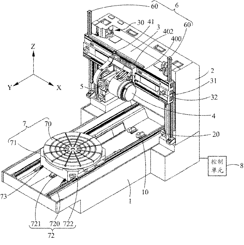
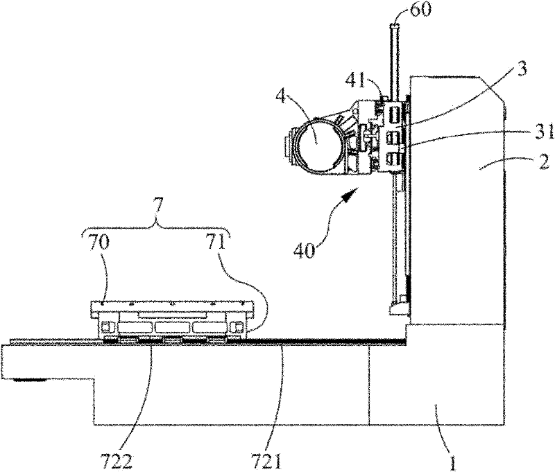
[0057] see figure 1As shown, the present invention is a moving beam machine tool, which has a machine platform 1, a column 2, a beam 3, a spindle saddle 4, a spindle head 5, a dynamic counterweight 6, a rotating working Station 7 and a control unit 8 .

[0058] The machine table 1 has three axes directions of X, Y, and Z, and at least one end of the machine table 1 has at least one Y-axis direction limiter 10 .

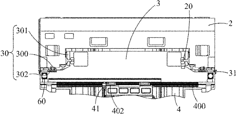
[0059] The upright column 2 is arranged at one end of the machine table 1 and is arranged perpendicular to the X-axis direction. At least one side of the upright column 2 and two ends of the side are respectively provided with a Z-axis direction limiter 20 .

[0060] The beam 3 is movably arranged on the column ...


PUM


Abstract

A moving beam type machine tool is disclosed, having a dynamic phase balancing weight set and a spindle saddle. The spindle saddle has at least one X-axis location feedback device. When the spindle saddle along the X-axis traverse, the at least one X-axis location feedback device is able to locate the spindle saddle and inform a controlling unit. The controlling unit changes the output pressure of the dynamic phase balancing weight set depending on the location of the spindle saddle, so that a crossbeam is able to maintain in a balancing state. The moving beam type machine tool is able to increase accurate, sensitivity of pressure response, withstanding weight and balancing state.

Description

technical field [0001] The invention relates to a moving beam machine tool, which relates to a dynamic counterweight, and the pressure of the dynamic counterweight can be changed according to the position of the main shaft saddle, so that the two ends of the beam can be maintained in a balanced state for use in Machine tools that improve precision, responsiveness to pressure, weight bearing and balance. Background technique [0002] The existing moving beam type gantry processing machine has a machine platform, a column is respectively arranged on both sides of the machine platform, a beam that can move longitudinally relative to the column is arranged between it, and a beam that can be vertically moved relative to the beam is provided at the beam. The main shaft saddle that moves left and right, the main shaft saddle is provided with a main shaft head that rotates relative to the main shaft saddle, and a worktable that can move back and forth relative to the machine table i...

Claims


Application Information

Patent Timeline
Patent Type & Authority Applications(China)
IPC IPC(8): B23Q1/01B23Q11/00B23Q17/24
CPCB23Q11/0028Y10T29/5114Y10T409/307672Y10T409/308288Y10T409/305712
Inventor 王仁杰张恩生陈志明
Owner IND TECH RES INST
Why Eureka
Try Eureka