
Plasma etching device, wafer fixture, and method for setting wafer

A technology for etching equipment and wafers, applied in chemical instruments and methods, circuits, crystal growth, etc., can solve the problems of no directionality, waste of space, increased working time and labor costs, etc., to achieve the best space utilization and improve production Effective, easy-to-locate effects

Inactive Publication Date: 2012-05-30
ZHISHENG SCI & TECH GUANGZHOU
View PDF2 Cites 3 Cited by
  • Summary
  • Abstract
  • Description
  • Claims
  • Application Information

AI Technical Summary

Problems solved by technology

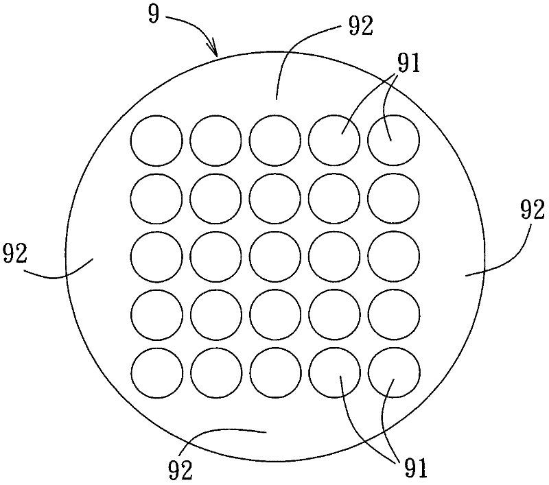
E.g figure 1 As shown, its width cannot accommodate one wafer accommodating groove 91 in the partial area 92 of the adjacent boundary (the outer area of ​​the wafer accommodating groove 91 arranged in a square), but the total area of ​​these regions 92 can also accommodate several more. wafer holding slot 91, so these areas 92 are wasted space
[0003] Furthermore, since the outer contour of the wafer fixture is circular and has no directionality, it is desired to place the wafer fixture carrying the wafer into plasma etching When the electrode is on the equipment, it is not easy to position the wafer fixture, so it is impossible to use the robot arm to automatically place it, which needs to increase the working time and labor cost

Method used


Image

  • Plasma etching device, wafer fixture, and method for setting wafer
  • Plasma etching device, wafer fixture, and method for setting wafer
  • Plasma etching device, wafer fixture, and method for setting wafer

Examples


Embodiment Construction

[0031] The present invention will be described in detail below in conjunction with the drawings and embodiments:

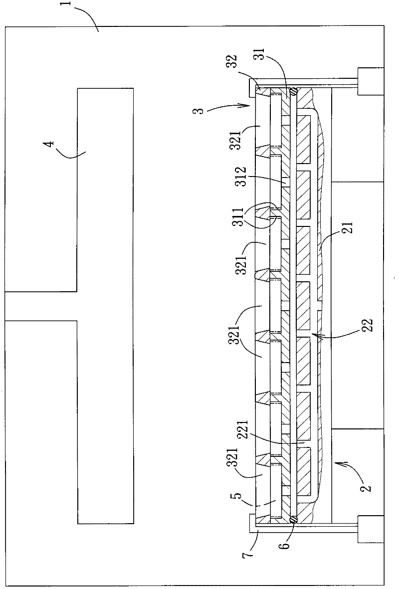
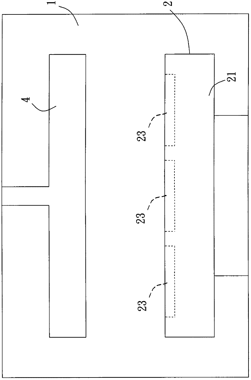
[0032] See figure 2 , The first preferred embodiment of the plasma etching equipment of the present invention can be provided with a plurality of wafers 5, including a reaction chamber 1, a bottom electrode 2, a wafer jig 3 and one set in the reaction chamber 1 It corresponds to the upper electrode 4 located above the lower electrode 2.

[0033] The lower electrode 2 is arranged in the reaction chamber 1, has a square body 21 and a cooling system 22. The cooling system 22 includes a plurality of air outlet holes 221 arranged on the top surface of the main body 21 and facing the wafer jig 3. In this embodiment, the cooling system 22 is connected to a gas supply system (not shown) outside the reaction chamber 1 so as to Cooling gas is provided when the wafer 5 is etched.

[0034] The wafer jig 3 covers the bottom electrode 2 and has a square bottom plate 31 and a cover ...


PUM


Abstract

The invention discloses a plasma etching device, a wafer fixture, and a method for setting a wafer. The plasma etching device comprises a reaction cavity, a lower electrode, a wafer fixture, and an upper electrode arranged inside the reaction cavity and opposite to the lower electrode. The lower electrode is arranged inside the reaction cavity and has rectangular body. The wafer fixture covers the body of the lower electrode and has a square base plate, wherein the base plate is provided with a plurality of wafer containing grooves, with each wafer containing groove capable of containing a wafer. The plasma etching device can contain a lot of wafers, reach the optimal space-utilizing rate, raise the production efficiency, be easily positioned, and make automatic of the flow of loading a wafer to be inside the reaction cavity.

Description

Technical field [0001] The invention relates to a plasma etching equipment and a wafer jig, in particular to a plasma etching equipment which can automatically load wafers, a wafer jig and a method for setting wafers. Background technique [0002] The existing plasma etching equipment for wafers uses circular electrodes, and the wafer-bearing jigs also match the electrodes with circular shapes. See figure 1 Since the outer contour of the wafer jig 9 is circular, and the general wafer accommodating grooves 91 are arranged in an array, and are generally arranged in a square shape, it is limited by the circular boundary of the wafer jig 9 so that the wafer The overall area of ​​the fixture 9 is not fully utilized. E.g figure 1 As shown, the width of the partial area 92 (the area outside the square arrangement of the wafer accommodating groove 91) of the adjacent boundary cannot accommodate a wafer accommodating groove 91, but the total area of ​​these areas 92 can also accommodate ...

Claims


Application Information

Patent Timeline
Patent Type & Authority Applications(China)
IPC IPC(8): C30B33/12H01L21/3065
Inventor 张宏隆陈庆安胡肇汇
Owner ZHISHENG SCI & TECH GUANGZHOU
Learn More