
Method for operating a combustion engine, control element, combustion engine

An engine, operating state technology, applied in engine control, engine components, combustion engines, etc., can solve problems such as affecting cylinder air charge, regardless of changes in mass flow, etc.

Inactive Publication Date: 2012-05-30
AUDI AG
View PDF7 Cites 3 Cited by
  • Summary
  • Abstract
  • Description
  • Claims
  • Application Information

AI Technical Summary

Problems solved by technology

[0006] A disadvantage of the known method and the engine is that the air mass sensor only detects the total fresh air volume fed to the engine, but does not take into account the changes in the mass flow occurring in the system
Therefore, previously it was not possible or only possible with the aid of additional sensors to take into account the amount of gas which additionally enters the intake manifold due to the ventilation of the crank chamber and which in turn affects the cylinder filling

Method used


Image

  • Method for operating a combustion engine, control element, combustion engine
  • Method for operating a combustion engine, control element, combustion engine
  • Method for operating a combustion engine, control element, combustion engine

Examples


Embodiment Construction

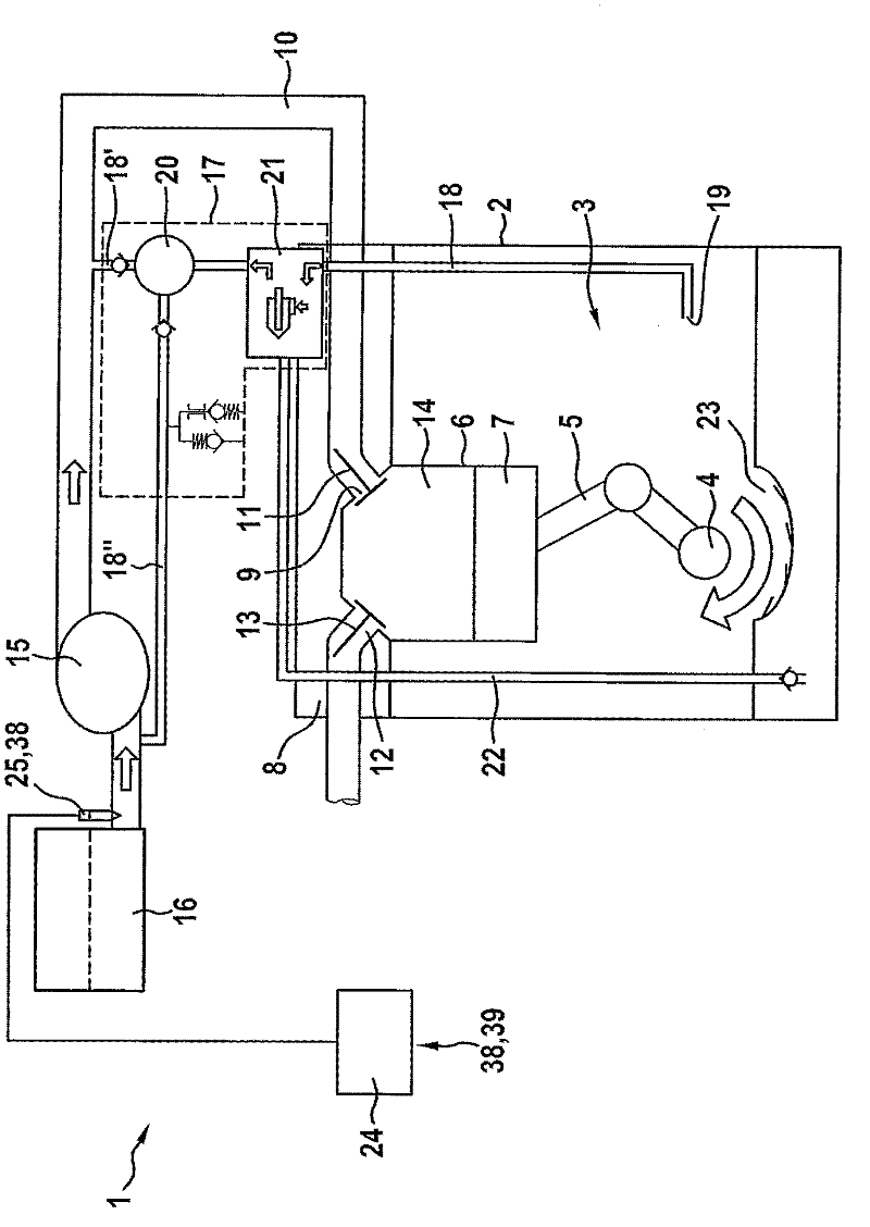
[0023] figure 1 A simplified illustration of an engine 1 of a motor vehicle is shown, which is not shown in detail here. The engine 1 includes a crankcase 2 forming a crank chamber 3 . A crankshaft 4 of the engine 1 is rotatably mounted in the crank chamber 3 . Also located in the crank chamber 3 are an oil sump / oil surface 23 and a connecting rod 5 driven by the crankshaft, which is connected in a conventional manner to a piston 7 movable axially in a cylinder 6 . Cylinder 6 is closed at the top by a cylinder head 8 of engine 1 , wherein an air intake 9 is formed in the cylinder head, into which an intake duct 10 for feeding fresh air into cylinder 6 opens. The air inlet 9 can be closed and opened by an actuatable valve 11 . Furthermore, the cylinder head 8 has an exhaust port 12 , which opens into the exhaust duct and which can be opened and closed by an actuatable valve 13 . Thus, the cylinder 6 , the cylinder head 8 and the piston 7 form a combustion chamber 14 of the ...


PUM


Abstract

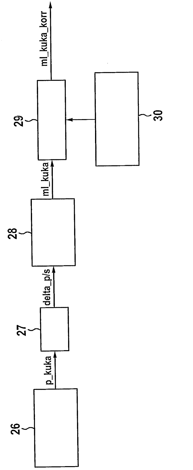
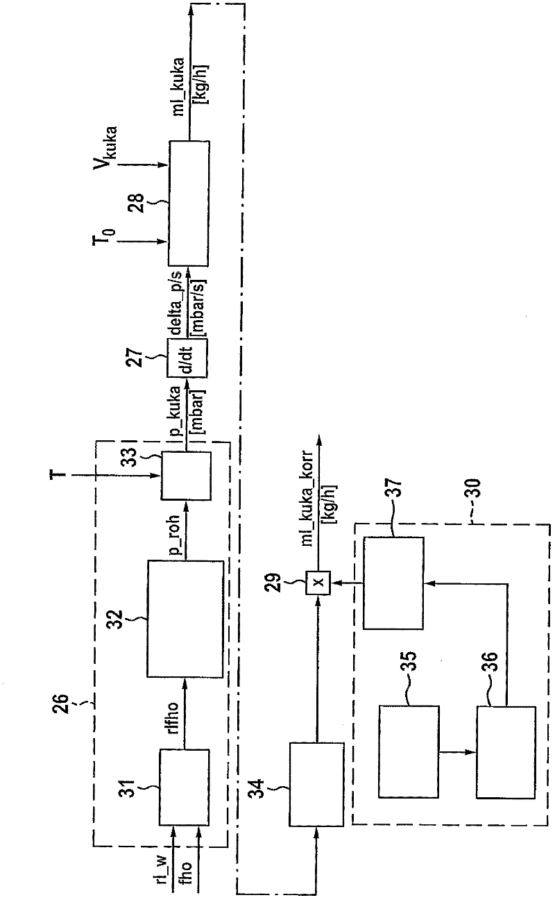
The invention relates to a method for operating an engine (1). The engine comprises at least one ventilation channel (18) leading to an intake tube (10) from a crank shaft chamber (3) of a crankcase, and an air flow sensor (25) used for detecting the fresh air flow mass input into the engine (1). According to the detected fresh air flow mass, the air inflation degree of at least one cylinder (6) of the engine (1) can be obtained. The method comprises the steps of: confirming the pressure (p_kuka) inside the crank shaft chamber (3) in operation and correcting the air inflation degree of the cylinder according to obtained pressure changes (delta-p / s) inside the crank shaft chamber (3). Moreover, the utility model relates to a control unit particularly applicable to the control equipment of an engine of a motor vehicle. Also, the utility model relates to an engine particularly applicable to a motor vehicle.

Description

technical field [0001] The invention relates to a method for operating an engine comprising at least one ventilation channel leading from a crank chamber of a crankcase into an intake duct and an air mass sensor for detecting a mass flow of fresh air fed into the engine, wherein Based on the detected fresh air mass flow rate, the cylinder filling degree / cylinder filling quantity of at least one cylinder of the engine is determined. [0002] Furthermore, the invention relates to a control component for a control device, in particular of an engine of a motor vehicle. [0003] Furthermore, the invention relates to an engine, in particular for a motor vehicle, having a crankcase and at least one cylinder, the crankcase forming a crank chamber, the at least one cylinder being equipped with an intake duct, wherein a ventilation duct opens out of the crank chamber. Intake pipe, the engine has an air mass sensor and a first device for detecting the fresh air mass flow input into the ...

Claims


Application Information

Patent Timeline
Patent Type & Authority Applications(China)
IPC IPC(8): F02D41/18
CPCF02D41/187Y02T10/42F02D2250/08F01M13/023F02D2200/0402F02M25/06F02D41/0002F01M13/00Y02T10/40
Inventor T·梅尔A·兰格
Owner AUDI AG
Learn More