Triaxial mechanical decoupling device and vibration testing system

A decoupling device and vibration test technology, applied in the field of mechanical environment test, can solve the problems that one-way vibration test can not meet the requirements of vibration environment test, lateral limit constraints of motion freedom, and can not truly reproduce the vibration environment, etc. The effect of strong anti-interference ability, easy maintenance, and convenient manual adjustment

Inactive Publication Date: 2012-05-30
BEIJING AREOSTANARD NEW TECH +1
View PDF7 Cites 23 Cited by
  • Summary
  • Abstract
  • Description
  • Claims
  • Application Information

AI Technical Summary

Problems solved by technology

[0002] In the real environment, the natural vibration environment of most products is a multi-directional, multi-degree-of-freedom compound vibration environment. The existing uniaxial vibrator cannot realize the vibration simulation of three axes at the same time.
Simultaneous vibration of the three axes requires the installation of single-degree-of-freedom exciters in the three axes, and the existing mechanical decoupling device connecting the working platform and the single-degree-of-freedom exciter easily leads to three single-degree-of-freedom vibrations There is strong motion cross-coupling between the vibration table itself and the degree of freedom of motion in the non-force transmission direction to produce lateral limit constraints
The use of uniaxial vibration test equipment and test methods will inevitably increase the test time. At the same time, the uniaxial vibration test method can restore the actual vibration environment poorly, and cannot truly reproduce the real vibration environment.
With the continuous improvement of product precision, reliability requirements and test efficiency, the one-way vibration test can no longer meet the test requirements of the vibration environment

Method used


Image

  • Triaxial mechanical decoupling device and vibration testing system
  • Triaxial mechanical decoupling device and vibration testing system
  • Triaxial mechanical decoupling device and vibration testing system

Examples


Embodiment Construction

[0021] A triaxial mechanical decoupling device and a vibration test system of the present invention will be introduced below in conjunction with the accompanying drawings and embodiments:

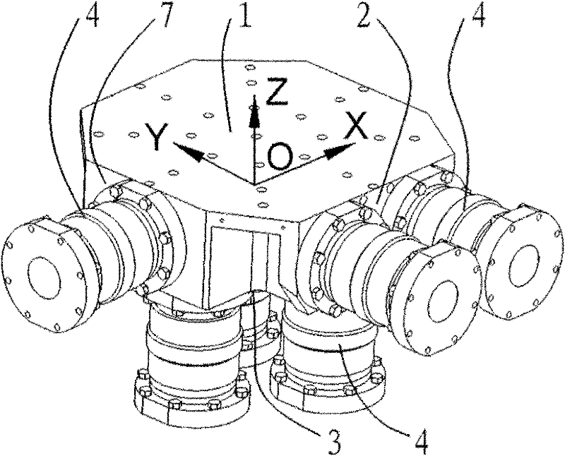
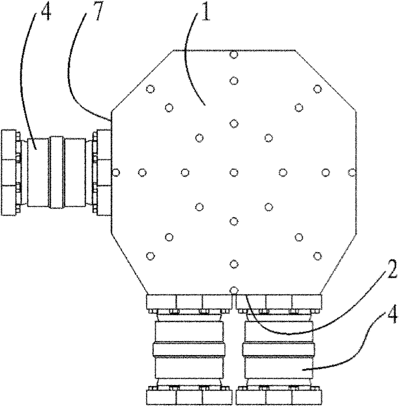
[0022] Such as figure 1 , 2 As shown, a three-axis mechanical decoupling device includes a working platform 1 and a spherical hydrostatic bearing 4 . The working platform 1 is in the shape of a metal plate, and two mounting surfaces perpendicular to each other and perpendicular to the upper and lower end surfaces of the working platform are provided on its side, so that the normal lines of the two mounting surfaces form a right angle with the normal lines of the upper and lower end surfaces of the working platform. In the coordinate system, the upward side of the normal line of the upper and lower end surfaces of the working platform is the Z direction, and the side of the normal line of a mounting surface is the X axis, so that the above mounting surface is the X-direction side of the wor...


PUM


Abstract

The invention belongs to the technical field of mechanical environmental test, particularly relates to a triaxial mechanical decoupling device and a vibration testing system, and provides a device for connecting a triaxial simultaneous excitation work bench and a testing system. The triaxial mechanical decoupling device is characterized by comprising a work bench (1) and spherical hydrostatic bearings (4), the work bench (1) is in the shape of a metal plate, two mutually perpendicular mounting faces which are perpendicular to the upper end face and the lower end face of the work bench are arranged on the lateral side of the work bench (1), the spherical hydrostatic bearings (4) are respectively mounted on the lower end face (3) of the work bench, an X-directional side (7) of the work bench and a Y-directional side (2) of the work bench, and the other side of each spherical hydrostatic bearing (4) is connected with a vibration generator. Triaxial composite vibration testing of a workpiece can be achieved by using the corresponding triaxial work bench and the spherical hydrostatic bearings. By means of the triaxial mechanical decoupling device, the workbench can move only in the Z-direction, the X-direction or the Y-direction, so that triaxial translation of the work bench is realized.

Description

technical field [0001] The invention belongs to the technical field of mechanical environmental tests, and in particular relates to a three-axis mechanical decoupling device and a vibration test system. Background technique [0002] In the real environment, the natural vibration environment of most products is a multi-directional, multi-degree-of-freedom compound vibration environment. The existing uniaxial vibrator cannot realize the vibration simulation of three axes at the same time. Simultaneous vibration of the three axes requires the installation of single-degree-of-freedom exciters in the three axes, and the existing mechanical decoupling device connecting the working platform and the single-degree-of-freedom exciter easily leads to three single-degree-of-freedom vibrations There is a strong motion cross-coupling between the vibration table itself and the degree of freedom of motion in the non-force transmission direction to produce lateral limit constraints. [0003...

Claims


Application Information

Patent Timeline
Patent Type & Authority Applications(China)
IPC IPC(8): G01M7/06F16M11/14F16M11/18
Inventor 周兴广张巧寿
Owner BEIJING AREOSTANARD NEW TECH
Why Eureka
Try Eureka