Axial limiting structure of collecting ring of electromotor

An axial limit and collector ring technology, applied in electrical components, electromechanical devices, etc., can solve the problems of loosening of the set screw, falling off of the motor, damage, etc., to achieve reliable axial limit, simple structure, easy to implement. Effect

Inactive Publication Date: 2012-05-30
TAIZHOU CITY YUANDA ELECTRIC MOTOR MFG
View PDF0 Cites 4 Cited by
  • Summary
  • Abstract
  • Description
  • Claims
  • Application Information

AI Technical Summary

Problems solved by technology

The axial limit structure of this kind of motor collector ring is simple and can play the role of axial limit. However, because the motor collector ring rotates with the motor rotor shaft, the set screw on the limit stop ring may be loosened and tightened. Once the set screw is loose, the limit retaining ring will shift, and it will not be able to act as an axial limit on the motor collector ring, and the motor collector ring will not be able to function. The limit retaining ring and the set screw will loosen or even fall off. cause internal damage to the motor

Method used


Image

  • Axial limiting structure of collecting ring of electromotor
  • Axial limiting structure of collecting ring of electromotor
  • Axial limiting structure of collecting ring of electromotor

Examples


Embodiment Construction

[0011] The present invention will be further described below according to the accompanying drawings and in conjunction with the embodiments.

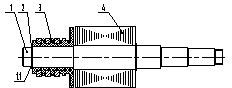
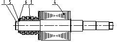
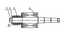
[0012] attached figure 2 Shown in the prior art motor collector ring axial limit structure, it is provided on the rotor shaft 1, the collector ring 3 and the electromagnetic winding 4 as the main components of the motor rotor assembly, the collector ring 3 is sleeved on the rotor shaft 1 The left end of the rotor shaft 1 is provided with a limit stop ring 5 at the left end face of the collector ring 3 on the rotor shaft 1, and a set screw 6 is provided on the limit stop ring 5, and the set screw 6 penetrates the limit stop ring 5 and is fastened to the rotor shaft. 1, so as to realize the axial limit of the motor collector ring. During the use of this structure, the limit retaining ring 5 will shift or fall off due to the loosening of the set screw 6, and cannot play an axial limit on the motor collector ring. If the screw 6 is loose...


PUM


Abstract

The invention discloses an axial limiting structure of a collecting ring of an electromotor. The axial limiting structure is arranged on an electromotor rotor assembly mainly comprising a rotor shaft, a collecting ring and an electromagnetic winding, wherein the collecting ring is sleeved at the left end of the rotor shaft; a ring groove is formed at the position of the left end surface of the collecting ring of the rotor shaft; and a circlip for a shaft is embedded in the ring groove to form the axial limiting structure of the collecting ring. The axial limiting structure disclosed by the invention has a simple structure and is simple in process and easy in realization; and the circlip for the shaft is adopted for axially limiting, so that the phenomena of loosening and falling can be avoided and the axial limiting of the collecting ring of the electromotor can be reliably realized.

Description

technical field [0001] The invention relates to a motor rotor structure, in particular to a motor rotor structure with a collector ring. Background technique [0002] The function of the motor collector ring is to cooperate with the commutator to realize mechanical commutation. The motor collector ring of the prior art is sleeved on the rotor shaft of the motor, and the end face of the motor collector ring is sleeved with a limit retaining ring, and the limit retaining ring A set screw is arranged on the upper part, and the set screw penetrates the limit retaining ring and is fastened on the rotor shaft of the motor, so as to realize the axial limit of the collecting ring of the motor. This kind of motor collector ring has a simple axial limit structure and can play an axial limit role. However, since the motor collector ring rotates with the rotor shaft of the motor, the set screws on the limit ring may be loosened and tightened. Once the set screw is loose, the limit reta...

Claims


Application Information

Patent Timeline
IPC IPC(8): H02K13/00
Inventor 丁玉林丁久斌朱静李文缪冬平王耀祖
Owner TAIZHOU CITY YUANDA ELECTRIC MOTOR MFG
Why Eureka
Try Eureka