X-ray Tomographic Inspection System For The Idendification Of Specific Target Items

An inspection system, X-ray technology, applied in the field of X-ray scanning

Inactive Publication Date: 2012-05-30
RAPISCAN SYST INC (US)
View PDF42 Cites 30 Cited by
  • Summary
  • Abstract
  • Description
  • Claims
  • Application Information

AI Technical Summary

Problems solved by technology

The algorithm often causes an alert for a baggage or cargo item, and the image data must be viewed by an operator

Method used


Image

  • X-ray Tomographic Inspection System For The Idendification Of Specific Target Items
  • X-ray Tomographic Inspection System For The Idendification Of Specific Target Items
  • X-ray Tomographic Inspection System For The Idendification Of Specific Target Items

Examples


no. 1 example

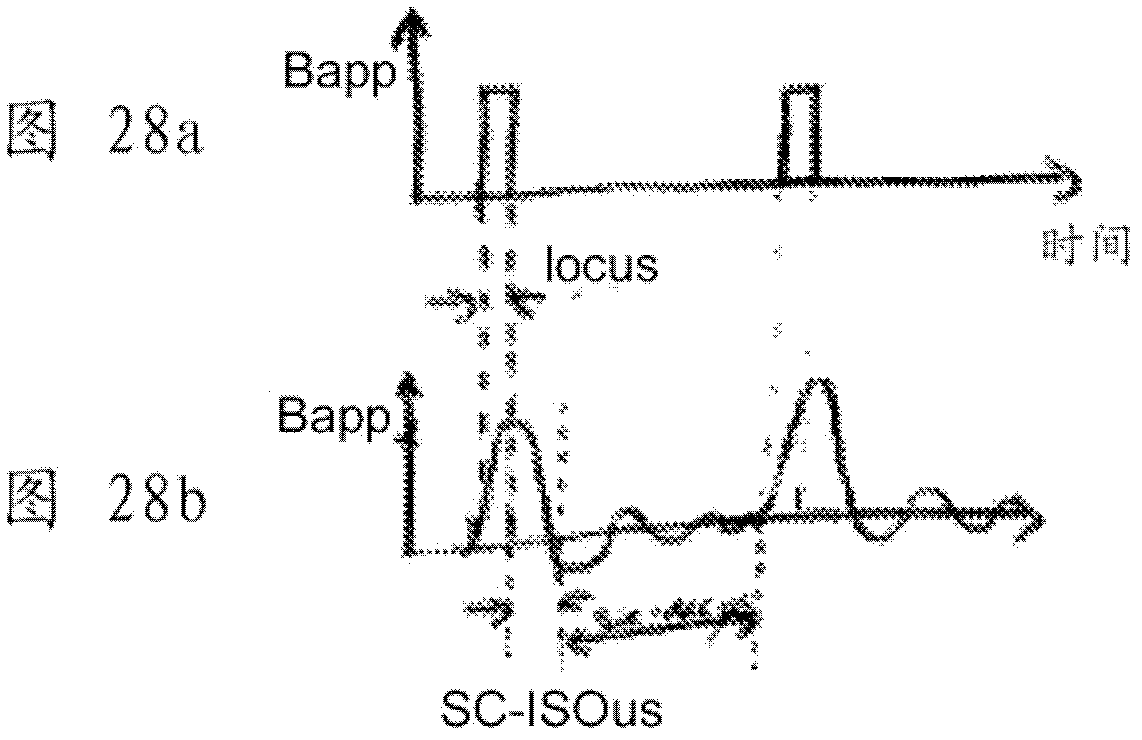
[0162] Confirming the first embodiment of the sensor: nuclear quadrupole resonance (NQR)

[0163] In one embodiment, the validation sensor includes a system that performs nuclear quadrupole resonance (NQR) measurements. Here, certain nuclei (especially nitrogen and chlorine) are known to have a significant magnetic quadruple moment. Typically, the magnetic quadrupole moments of independent spin nuclei in a material sample are arranged in random orientations. Under the application of a strong external magnetic field, the independent magnetic quadrupole moments of the nuclei in the material under examination align with the applied magnetic field, forming a weak magnetic field acting in the opposite direction of the applied field. The applied field may be in the range of 10 to 100 mTesla, whereas the field produced by aligned nuclei may only be in the femtotesla range. Once the applied magnetic field is turned off, the magnetic dipoles start to move out of alignment, and the ma...

no. 2 example

[0173] Confirmation of the second embodiment of the sensor: X-ray diffraction

[0174] In another embodiment, the confirmation sensor includes an X-ray diffraction system. X-rays in the range of 10keV to 200keV have associated wavelengths commensurate with the lattice spacing in known materials. The wavelength of 10keV X-rays is 1.24×10 -10 m (1.24 Angstroms), and the wavelength of 200keV X-rays is 6×10 -12 m (0.06 Angstroms). In cases where the wavelength of the wave and the spacing of the scattering objects through which the wave propagates are close to the wavelength, then diffraction of the wave will occur according to the Bragg diffraction condition:

[0175] nλ=2dsinθ

[0176] where n=order of the diffraction pattern, λ=wavelength of the wave, d=lattice spacing, and θ=diffraction angle.

[0177] In the case of X-rays, Bragg diffraction can be used to determine the lattice spacing and thus the material type. In a practical X-ray system, the X-ray source produces not...

no. 3 example

[0194] Confirming the third embodiment of the sensor: X-ray backscatter (backscatter) imaging

[0195] In another embodiment, the validation sensor includes an X-ray backscatter imaging system.

[0196] X-ray backscattering occurs when X-rays undergo Compton interactions. Here, the scattered X-rays are left with less energy than before the collision, and the difference in energy is transferred to electrons in the material under examination. Scattered X-rays are likely to be scattered back in the direction from which they came, and this backscattered X-rays can be detected by one or more X-ray sensors arranged adjacent to the X-ray source. The direction of the scattered X-rays is independent of the direction of the input beam, and therefore there is only a weak spatial correlation between the backscatter signal from a particular object and the detection signal of the backscatter signal.

[0197] Therefore, a collimator is preferably incorporated into the system, between the X...


PUM


Abstract

The present invention provides for an improved scanning process with a stationary X- ray source arranged to generate X-rays from a plurality of X-ray source positions around a scanning region, a first set of detectors arranged to detect X-rays transmitted through the scanning region, and at least one processor arranged to process outputs from the first set of detectors to generate tomographic image data. The X-ray screening system is used in combination with other screening technologies, such as NQR-based screening, X-ray diffraction based screening, X-ray back-scatter based screening, or Trace Detection based screening.

Description

[0001] Cross References to Related Applications [0002] This application is based upon US Patent Provisional Application No. 61 / 181,070, filed May 26, 2009, for priority purposes. [0003] This application is also a continuation-in-part of U.S. Patent Application No. 12 / 485,897, filed June 16, 2009, which is a continuation-in-part of U.S. Patent Application No. 10 / 554,656, filed October 25, 2005 Continuing, and now granted US Patent No. 7,564,939, which is the 371 National Phase Application of PCT / GB04 / 01729 filed 23 April 2004 and in turn based on UK Application No. 0309387.9 filed 25 April 2003, used as priority. [0004] This application is also a continuation-in-part of U.S. Patent Application No. 12 / 371,853, filed February 16, 2009, which is a continuation-in-part of U.S. Patent Application No. 10 / 554,975, filed October 25, 2005 Continuing, and now granted US Patent No. 7,512,215, which is the 371 National Phase Application of PCT / GB2004 / 01741 filed 23 April 2004 and in ...

Claims


Application Information

Patent Timeline
Patent Type & Authority Applications(China)
IPC IPC(8): G21K1/12
CPCH01J35/24G01V5/0041H01J35/06H01J35/045H01J2235/068G01V5/0025G01T1/1603G01V5/005H01J35/153G01V5/0008G01V5/0033G01V5/0058
Inventor E.J.莫顿
Owner RAPISCAN SYST INC (US)
Why Eureka
Try Eureka