Filling flux welding wire

A technology of filler welding and welding wire, applied in the direction of welding medium, welding equipment, welding/cutting medium/material, etc., can solve the problems of insufficient high temperature crack resistance of mild steel, no direction of composition design, no specific details, etc. , to achieve the effects of superior mechanical properties, superior quality, superior high temperature crack resistance

Inactive Publication Date: 2012-06-06
KOBE STEEL LTD
View PDF6 Cites 9 Cited by
  • Summary
  • Abstract
  • Description
  • Claims
  • Application Information

AI Technical Summary

Problems solved by technology

However, as a method of improving the high-temperature crack resistance of mild steel, which is the object of the present invention, no specific method is shown for the method of controlling the solidification mode, and the direction of composition design is not given.
[0017] In addition, even if the solidification mode prediction formula proposed for stainless alloys is applied to mild steel, the solidification mode prediction formula is originally constructed for stainless alloys, so there is a solidification mode when it is applied to mild steel, etc. The problem of low prediction accuracy
[0018] Furthermore, as shown in Patent Document 3, in "controlling to advance the crystallization time of austenite or delta ferrite crystallized after the primary phase crystallization, fracture cracks are generated by dividing the liquid phase remaining in the form of a film." In this idea, how to improve the high temperature crack resistance of mild steel, which is the object of the present invention, is not enough.
This is because the solidification mode of mild steel and the like in the composition range is already "FA mode", and even if the above considerations are applied, the high temperature crack resistance cannot be further improved
Therefore, in the improvement method of Patent Document 3, it is currently impossible to obtain sufficient high-temperature cracking resistance for the recent further improvement of welding work efficiency.

Method used


Image

  • Filling flux welding wire
  • Filling flux welding wire
  • Filling flux welding wire

Examples


Embodiment Construction

[0058] The filled flux welding wire of the present invention will be described in detail.

[0059] The flux-filled welding wire of the present invention is used for welding steel plates made of mild steel or high-tensile steel. In addition, the flux-filled welding wire of the present invention is suitable for use in gas shielded arc welding, and although it exhibits an excellent effect in single-face butt joint welding, the welding method is not particularly limited.

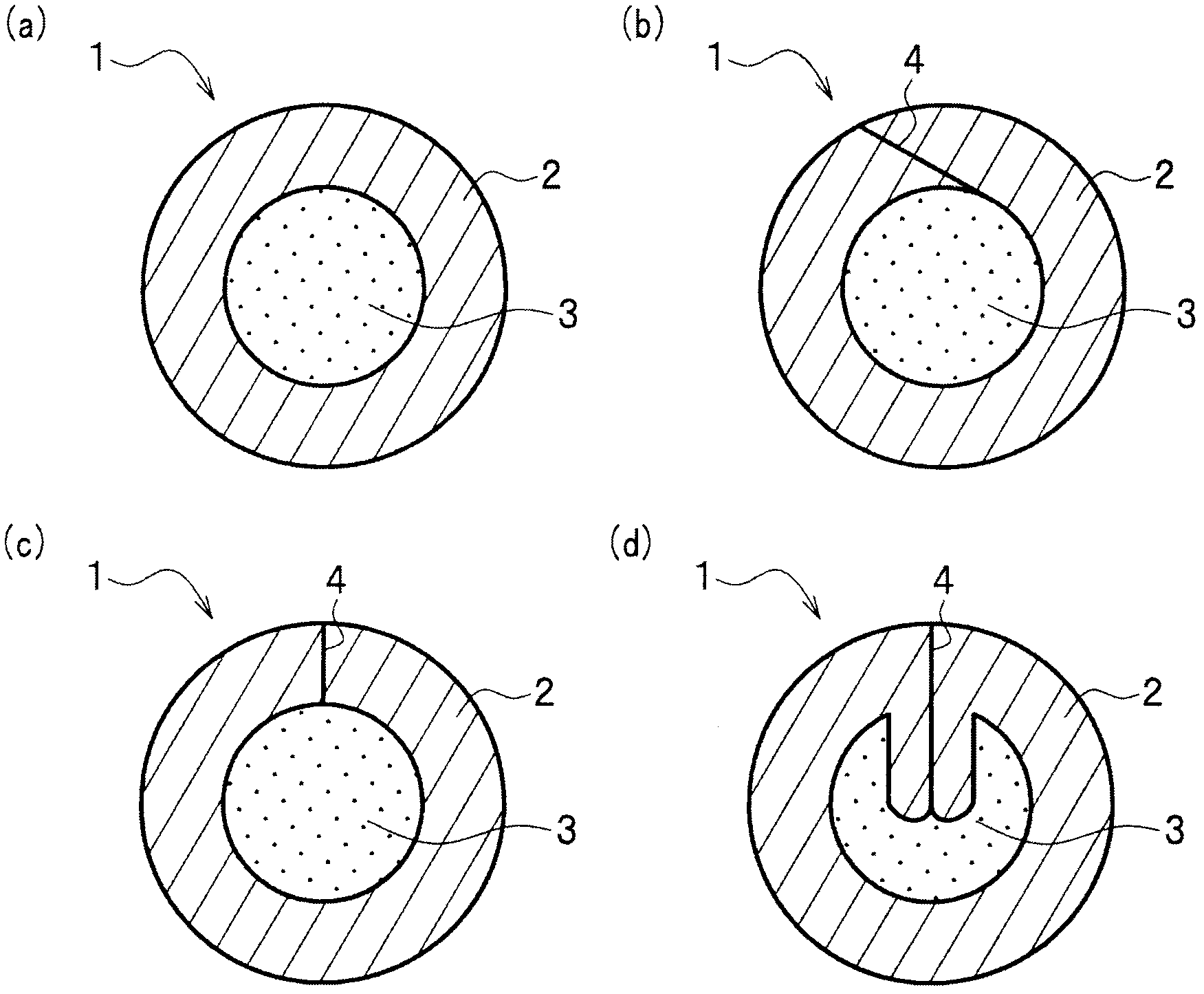
[0060] Such as figure 1 As shown in (a) to (d), a flux-filled welding wire (hereinafter referred to as welding wire) 1 is composed of a cylindrical steel sheath 2 and flux 3 filled in the cylinder. Also, wire 1 can be figure 1 As shown in (a), a seamless type in which flux 3 is filled in a tube of steel sheath 2 without joints may be figure 1 Any form of the seamed type in which the flux 3 is filled in the cylinder of the steel sheath 2 having the seam 4 as shown in (b) to (d).

[0061] Furthermore, in the w...


PUM

PropertyMeasurementUnit
diameteraaaaaaaaaa

Abstract

The invention provides a filling flux welding wire, which possesses the advantages of high temperature resistance of the primary layer welding part, which is welded by a single layer joint of the steel plate formed by the soft steel and the high tension steel, and welding operation performance as well as the welding metal machinery performance of the integral gesture welding. The invention is a filing flux welding wire used for the welding of the steel plates formed by the soft steel or the high tension steel and of the filling flux welding wire formed by filling the flux in the steel outer skin. The invention is characterized in that the required volume of the welding flux filling rate is a welding wire integral quality, and compared to the required volume of the welding wire integral quality, the invention comprises C, Si, Mn, Ti, TiO2,A1, A12O3,B,N,Ni(including0%), Cu(including0%), and the invention satisfies the equation that 10 equal to or larger than (Ni+14*C+0.29*Mn+0.30*Cu) / (1.5*Si) larger than or equal to 2.5(symbol of element represents the content of the element (mass percent)).

Description

technical field [0001] The present invention relates to a filled flux welding wire used for gas-shielded arc welding of steel plates made of mild steel or high-tensile steel, and more particularly to a titanium dioxide-based filled flux welding wire. Background technique [0002] Filled flux wires used for welding steel plates made of mild steel and high-tensile steel are increasing year by year due to their better weld bead appearance, better welding workability and superior deposition efficiency than solid wires. However, since the welding speed of the filled-flux welding wire is higher than that of the solid welding wire, high-temperature cracks tend to be easily generated especially at the root welding portion of the single-face butt joint welding. As a method of suppressing the occurrence of such high-temperature cracks, the following techniques are proposed. [0003] For example, Patent Document 1 proposes a method for improving high-temperature crack resistance by pe...

Claims


Application Information

Patent Timeline
Patent Type & Authority Applications(China)
IPC IPC(8): B23K35/368
CPCB23K35/3608B23K35/361B23K35/368C22C38/002C22C38/005C22C38/02C22C38/04C22C38/08C22C38/14C22C38/16
Inventor 岛本正树石田齐坂本浩一笹仓秀司柿崎智纪
Owner KOBE STEEL LTD
Why Eureka
Try Eureka