
Pneumatic valve for braking system of truck

A braking system, pneumatic valve technology, applied in the direction of control valve and air release valve, brake, brake components, etc., can solve problems such as hidden safety hazards, traffic accidents, brake system control delay, etc., to achieve good sealing performance and response. Speed ​​block, control speed effect

Inactive Publication Date: 2012-06-06
上海飞力普斯工业车辆零配件制造有限公司
View PDF0 Cites 0 Cited by
  • Summary
  • Abstract
  • Description
  • Claims
  • Application Information

AI Technical Summary

Problems solved by technology

However, the internal spool of the existing pneumatic valve is a rotating structure, which causes the pneumatic valve to act for too long, resulting in a delay in the control of the braking system and a long reflection time of the closing signal, which is likely to cause serious traffic accidents and pose serious safety hazards.

Method used


Image

  • Pneumatic valve for braking system of truck
  • Pneumatic valve for braking system of truck
  • Pneumatic valve for braking system of truck

Examples


Embodiment Construction

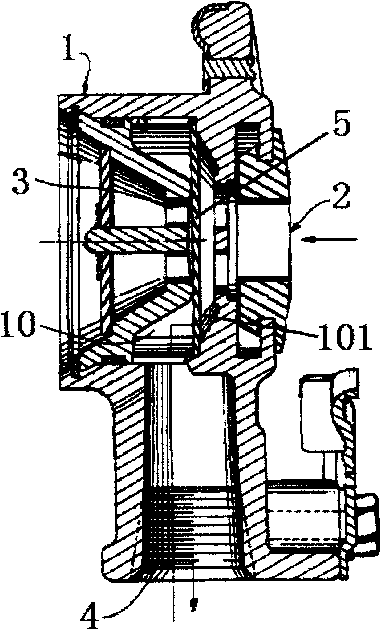
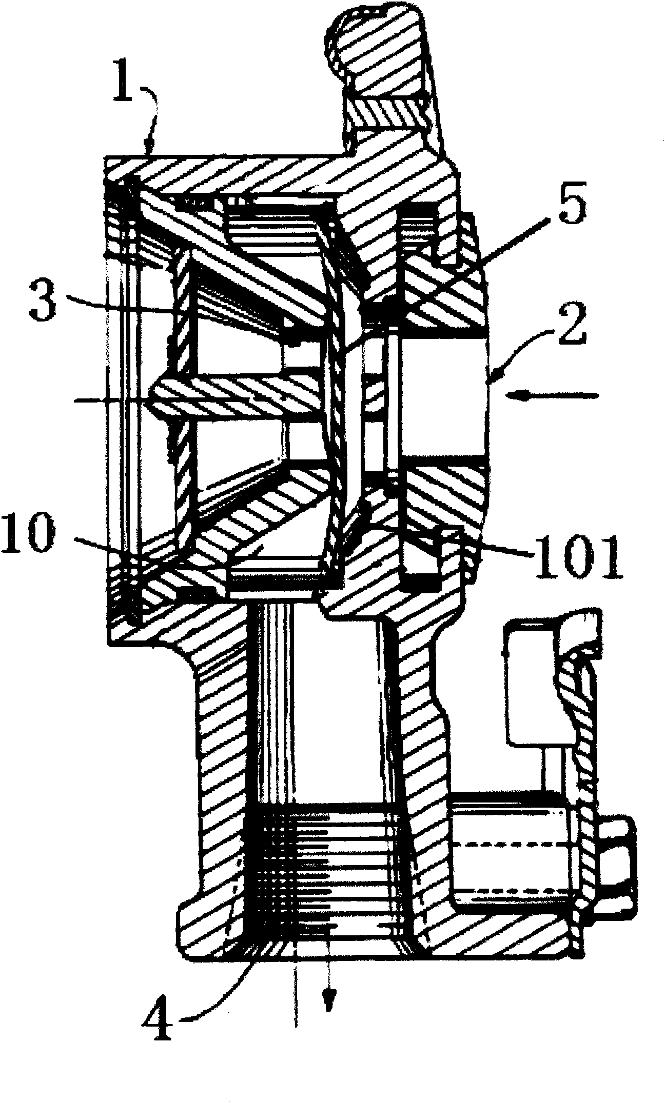
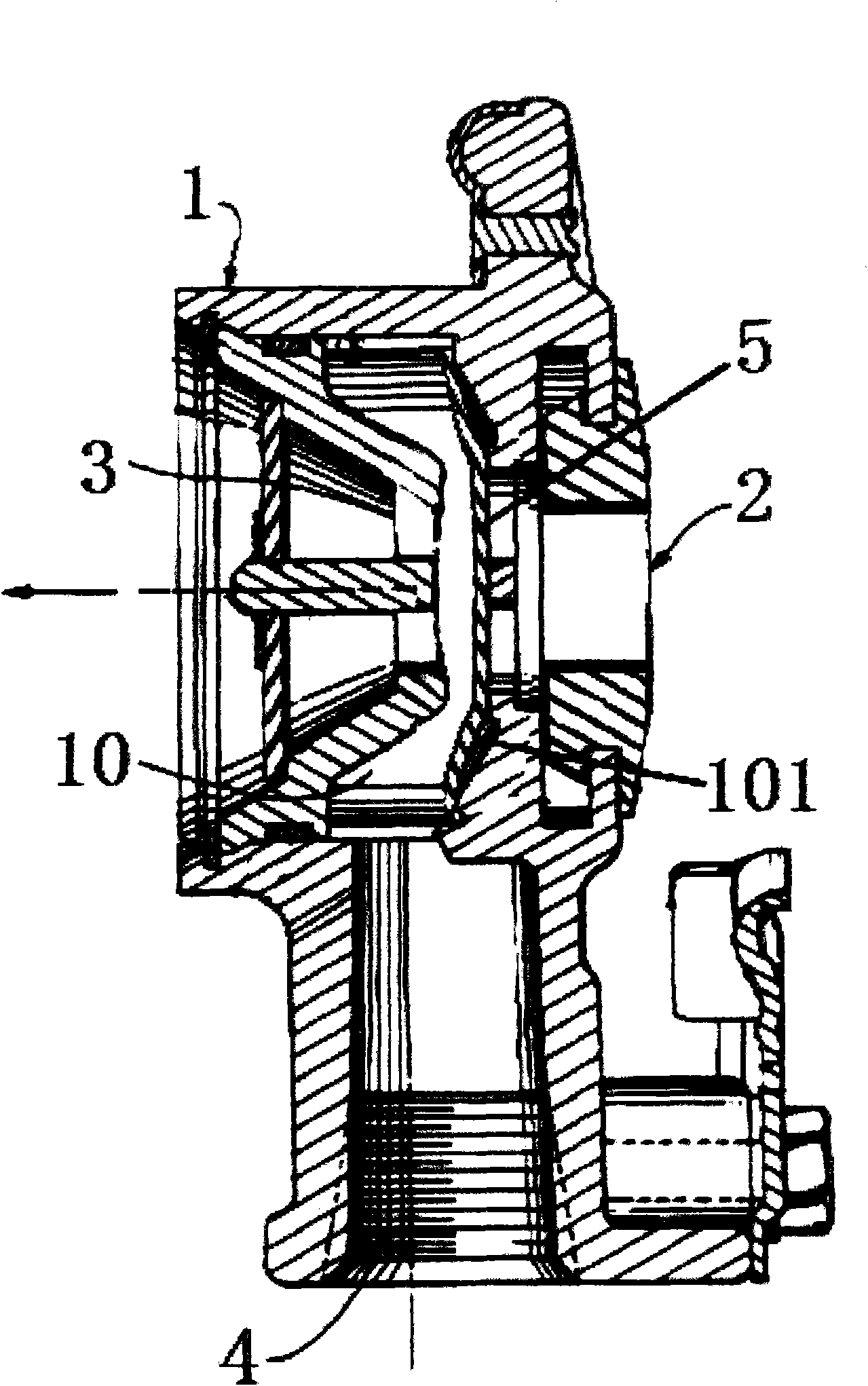
[0018] Such as figure 1 As shown, the pneumatic valve for the truck brake system according to the embodiment of the present invention includes a valve body 1 with a valve cavity 10, and the valve body 1 is provided with an air inlet 2 and an exhaust port respectively connected with the valve cavity 10. 3 and air outlet 4, the valve cavity 10 is provided with an elastic seal 5 that closes the exhaust port 3 when the pneumatic valve is inflated, and closes the air inlet 2 when the pneumatic valve is deflated. The elastic seal 5 is located between the air inlet 2 and Between exhaust ports 3.

[0019] In this embodiment, an annular seat 101 is provided in the valve chamber 10 , and the elastic sealing member 5 is fixed on the annular seat 101 .

[0020] In this embodiment, the axes of the air inlet 2 and the air outlet 3 are the same.

[0021] In this embodiment, the exhaust port 3 is an annular hole. The outside of the exhaust port 3 is provided with a trumpet-shaped exhaust p...


PUM


Abstract

The invention discloses a pneumatic valve for a braking system of a truck, which comprises a valve body (1) with a valve cavity (10), wherein an air inlet (2), an air exhaust port (3) and an air outlet (4) which are respectively communicated with the valve cavity (10) are arranged on the valve body (1), an elastic sealing component (5) which is used for sealing the air exhaust port (3) when the pneumatic valve is inflated and sealing the air inlet (2) when the pneumatic valve is deflated is arranged in the valve cavity (10), and the elastic sealing component (5) is positioned between the air inlet (2) and the air exhaust port (3). The pneumatic valve for the braking system of the truck has the advantages of high response speed, good sealing performance and high safety and reliability.

Description

technical field [0001] The invention relates to the field of automobile braking, in particular to a pneumatic valve used in a truck braking system. Background technique [0002] The trailer of the truck generally has an air brake, and the air brake is connected to the air pressure source of the tractor of the truck through a hose. In order to control the air pressure, a pneumatic valve is usually installed on the hose. However, the internal spool of the existing pneumatic valve is a rotating structure, which causes the pneumatic valve to act for too long, causes a delay in the control of the braking system, and takes a long time to reflect the closing signal, which is likely to cause serious traffic accidents and has serious safety hazards. Contents of the invention [0003] The present invention aims at the defects of the above-mentioned prior art, and provides a pneumatic valve for a truck brake system with fast response speed, good sealing performance, safety and relia...

Claims


Application Information

Patent Timeline
Patent Type & Authority Applications(China)
IPC IPC(8): B60T15/52
Inventor 李鹏
Owner 上海飞力普斯工业车辆零配件制造有限公司
Learn More