

Detection device for tunnel detection vehicle
A technology of a detection device and a detection vehicle, which is applied in the field of detection devices, can solve the problems of ballast in the tunnel lining, dangerous running of trains, collapse, etc., and achieves the effect of reducing the working intensity and improving the working efficiency.
- Summary
- Abstract
- Description
- Claims
- Application Information
AI Technical Summary
Problems solved by technology
Method used
Image

Examples
Embodiment Construction
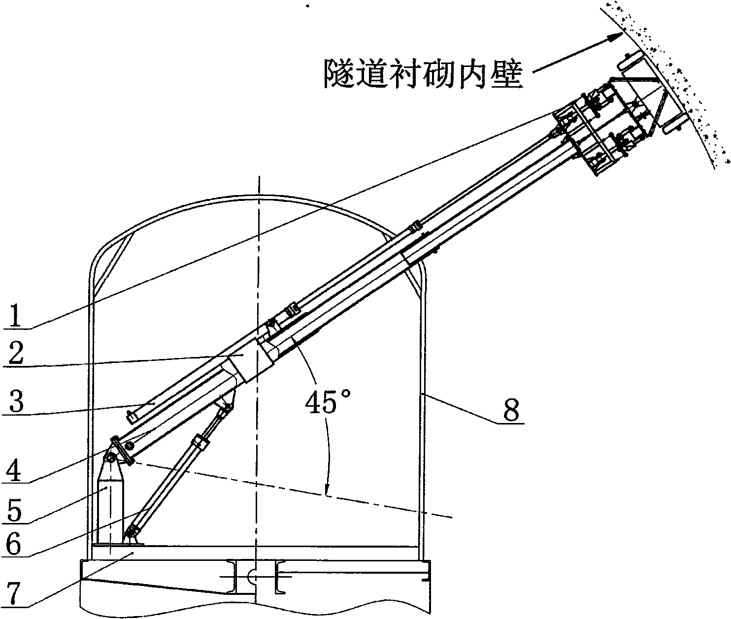
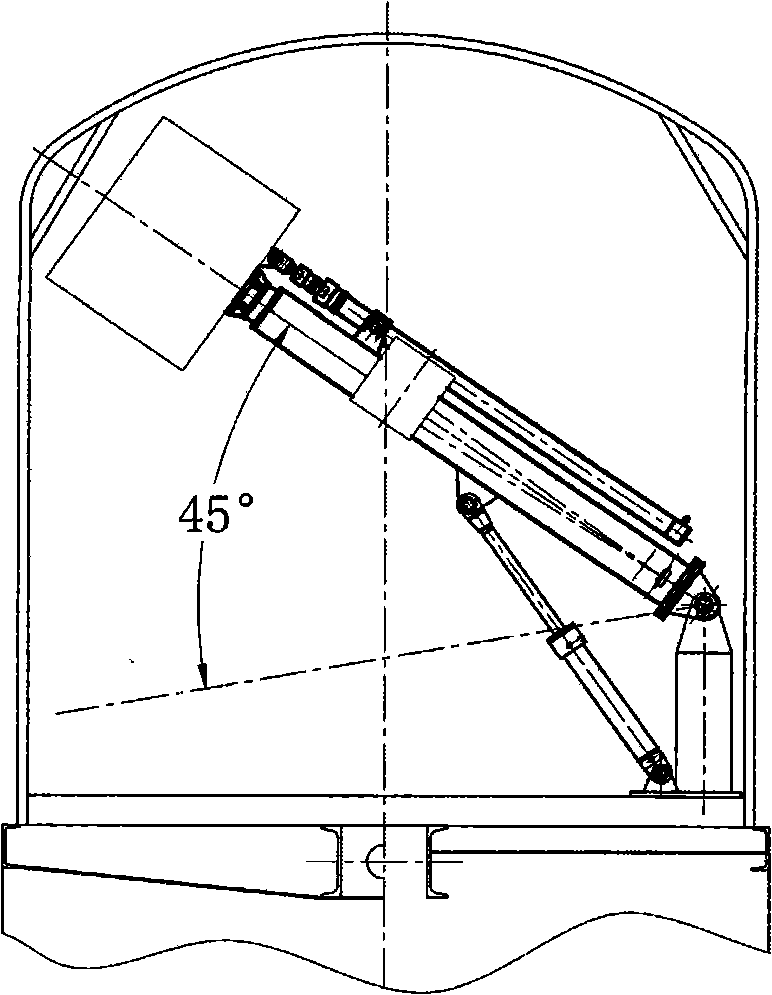
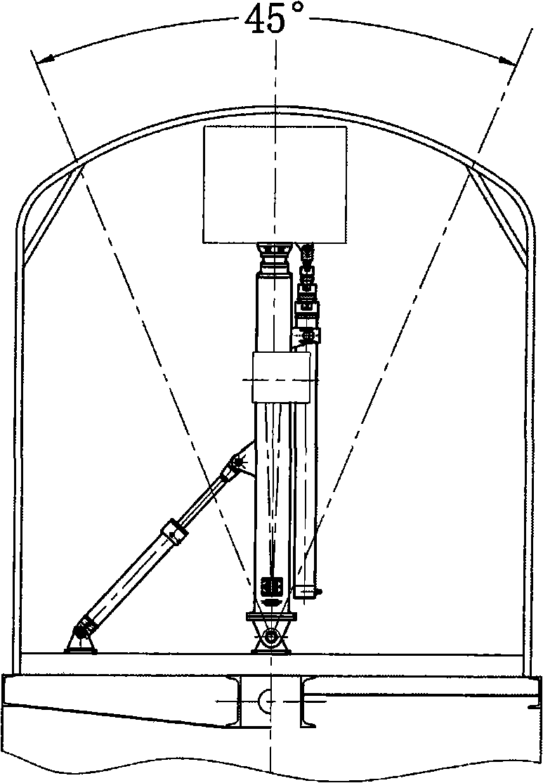
[0015] figure 1 In the shown embodiment, the base of the radar trolley 1 is fixed on the top of the innermost sleeve of the multi-stage telescopic arm 4, and the bottom of the outermost sleeve of the multi-stage telescopic arm 4 is connected to the No. 1 detection arm seat 5 through a pin shaft. , the hydraulic winch and the wire rope 2, the outermost piston rod of the multistage plunger hydraulic cylinder 3 are respectively installed on the outermost sleeve of the multistage telescopic arm 4 through bolt connection, the outermost stage of the multistage plunger hydraulic cylinder 3 The top of the inner piston rod is connected to the radar trolley 1, and the two ends of the swing hydraulic cylinder 6 are respectively connected to the outermost sleeve of the multi-stage telescopic arm 4 and the No. 1 detection arm base 5 through pin shafts. The whole set of detection arm is installed on the platform 7 of the detection vehicle. Before operation, after opening the vehicle shield...
PUM
 Abstract
Description
Claims
Application Information