Workpiece positioning device

A technology of positioning device and workpiece, applied in positioning device, feeding device, storage device, etc., can solve the problems of complex structure and poor positioning accuracy.

Active Publication Date: 2012-06-13
JIER MACHINE TOOL GROUP
View PDF7 Cites 13 Cited by
  • Summary
  • Abstract
  • Description
  • Claims
  • Application Information

AI Technical Summary

Problems solved by technology

[0005] Therefore, in order to overcome the defects of complex structure and poor positioning accuracy of the current workpiece position

Method used


Image

  • Workpiece positioning device
  • Workpiece positioning device
  • Workpiece positioning device

Examples


Embodiment Construction

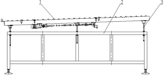
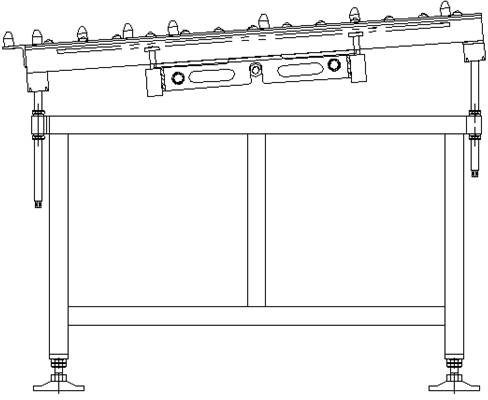
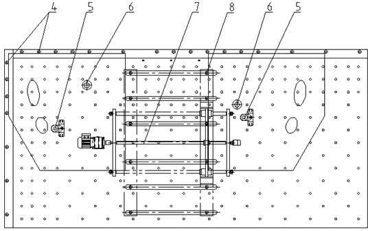
[0025] Refer to the attached figure 1 with 2 The shown workpiece positioning device includes a table 1, which is a state of use in the figure. It can be seen from the combination of the two figures that the rectangular table shown in the figure is a diagonally inclined table. Correspondingly, one corner of the table is the reference corner, for image 3 In the upper left corner of the table, the table forms an inclined table whose reference angle is lower than other parts of the table, and the inclination angle is greater than the friction angle of the workpiece to be positioned on the table; The positioning element is used to constrain the degree of freedom of the workpiece sliding on the table, and the corresponding two degrees of freedom are orthogonal.

[0026] It should be noted that the limitation on the friction angle is a basic condition, and it should be slightly larger than this value in actual use. Those skilled in the art can select it through the working hours o...


PUM


Abstract

The invention discloses a workpiece positioning device, which comprises a table top. An angle of the table top is a reference angle, so that the table top is inclined, the reference angle is lower than other portions of the table top, and an inclination angle is larger than a friction angle of a workpiece to be positioned on the table top. Correspondingly, two edges of the table top for limiting the reference angle are respectively provided with a positioning part for restraining the workpiece on the table top, and two corresponding degrees of freedom are orthogonal. The workpiece positioning device is simple in structure and high in positioning precision.

Description

technical field [0001] The invention relates to a workpiece positioning device, which is applied on an assembly line to facilitate the accuracy of feeding. Background technique [0002] In an automated production line, such as a stamping line, automatic feeding has relatively high technical requirements to meet the needs of robots to quickly and accurately pick up workpieces. Therefore, the first process of loading should be accurate and fast, which requires that the workpiece must have an accurate position on the loading table, especially the centering position, and then the basic requirement for the workpiece positioning device is to be able to quickly align the unstacking robot Or the position deviation generated by the workpiece transported by the conveyor belt can be quickly and accurately adjusted. [0003] Such positioning devices currently used in production practice mainly include visual centering systems and mechanical stopper centering devices, of which the forme...

Claims


Application Information

Patent Timeline
IPC IPC(8): B21D43/00
Inventor 赵昕颢张志刚卢建生李美霞
Owner JIER MACHINE TOOL GROUP
Why Eureka
Try Eureka