Coiled material conveying tensioning device

A tensioning device and tensioning technology, applied in the direction of winding strips, transportation and packaging, thin material handling, etc., can solve the problems of affecting the progress of the production process, intricate rollers, time-consuming and laborious, etc., to avoid poor guiding movement, Responsive effect

Active Publication Date: 2012-06-13
CHERY AUTOMOBILE CO LTD
View PDF9 Cites 40 Cited by
  • Summary
  • Abstract
  • Description
  • Claims
  • Application Information

AI Technical Summary

Problems solved by technology

[0003] The known tensioning devices generally adjust the tension through the mechanical structure, such as adjusting the position of the tensioning roller through the screw pair, or through the swing arm. The structure is complex, the volume is huge, and the guide rollers are intricate, which easily leads to the guiding movement of the coil. It is not smooth, cannot be adjusted quickly and automatically in real time, and when used for a long time, the tensioning device will be worn and the tensioning effect will be reduced. The process of repairing and adjusting the tension is time-consuming and laborious, which will affect the progress of the entire production process.

Method used


Image

  • Coiled material conveying tensioning device
  • Coiled material conveying tensioning device
  • Coiled material conveying tensioning device

Examples


Embodiment 1

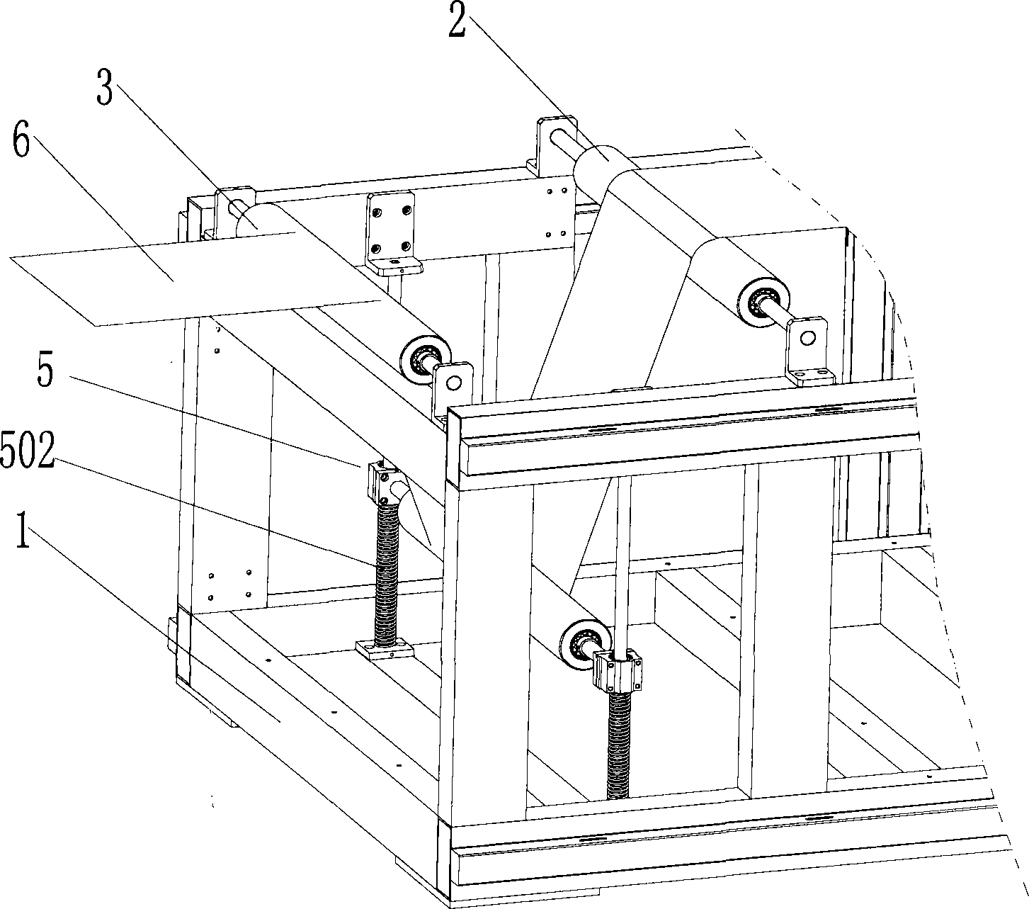
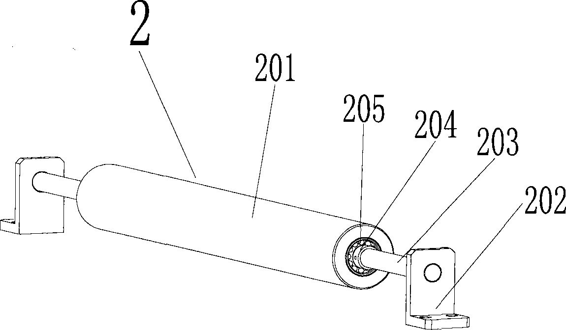
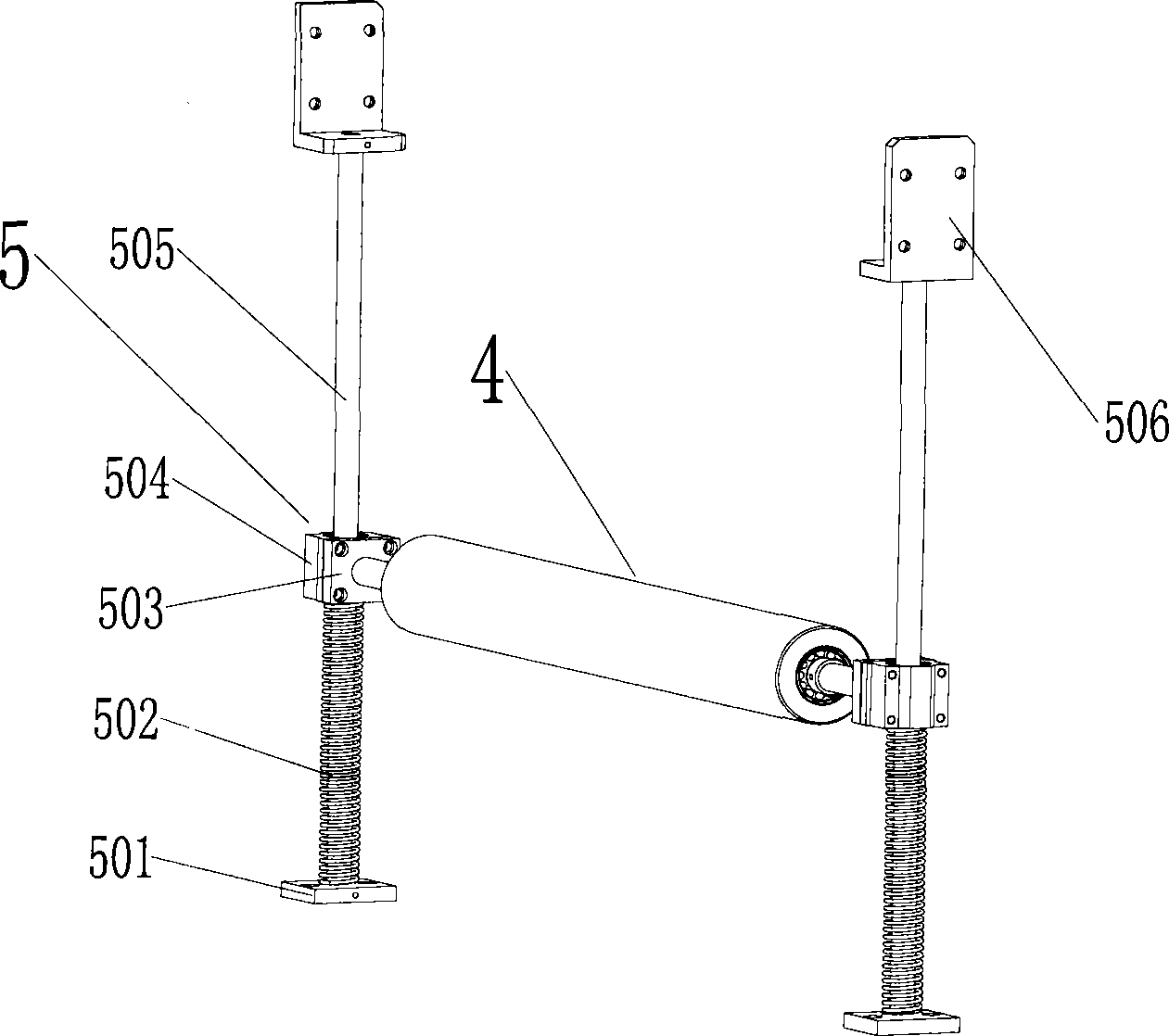
[0032] Such as figure 1 As shown, in this embodiment, the coil conveying tensioning device includes a workbench support 1 and a first guide roller assembly 2, a second guide roller assembly 3, and a tension guide roller assembly arranged on the workbench support 1. 4 and the tension guide roller bracket assembly 5, the first guide roller assembly 2 and the second guide roller assembly 3 are arranged on the upper part of the workbench bracket, and the tension guide roller bracket assembly 5 is arranged on the first Between the guide roller assembly 1 and the second guide roller assembly 2 , both ends of the tension guide roller assembly 4 are erected on the tension guide roller bracket assembly 5 . The axes of the first guide roller assembly 2 , the second guide roller assembly 3 and the tension guide roller assembly 4 are parallel.

[0033] The first guide roller assembly includes a first guide roller, the second guide roller assembly includes a second guide roller, the tensi...

Embodiment 2

[0050] Such as Figure 11 As shown, the structure of the coil conveying tensioning device in this embodiment is basically the same as that in Embodiment 1, the difference is that: the tension guide roller support assembly 5 also includes two limit switches 509, the Two limit switches 509 are respectively set on the guide rod 505 corresponding to the maximum tension position and the maximum compression position of the spring 502 . In this way, when the spring 502 reaches the maximum tension position or the maximum compression position, the limit switch 509 will prevent the tension guide roller assembly 4 from further moving upwards or downwards, so as to prevent the coil 6 from being broken.

[0051] Other structures in this embodiment are the same as those in Embodiment 1, and will not be repeated here.

[0052] From the above detailed description of the embodiments of the present invention, it can be understood that the present invention solves the problems of complex tensio...


PUM


Abstract

The invention provides a coiled material conveying tensioning device, which comprises a working platform support (1), and a first guide roller assembly (2), a second guide roller assembly (3), a tensioning guide roller assembly (4) and a tensioning guide roller support assembly (5), which are arranged on the working platform support, wherein the tensioning guide roller support assembly (5) is arranged between the first guide roller assembly and the second guide roller assembly, and the tensioning guide roller assembly is supported on the tensioning guide roller support assembly and below the first guide roller assembly and the second guide roller assembly; the tensioning guide roller support assembly can regulate the height of the tensioning guide roller assembly to allow a coiled material to be tensioned after the coiled material passes through a first guide roller, a tensioning guide roller and the second guide roller. The coiled material conveying tensioning device with a simple structure has the advantages of quick response and automatic regulation of the tension of the coiled material at a feeding end.

Description

technical field [0001] The invention relates to a coil conveying tensioning device. Background technique [0002] At present, large-scale coil processing machines such as general coating machines, film laminating machines, and compound machines are generally equipped with tensioning devices during the coil conveying stage. Slippage on the drive pulley inside the machine or excessive deflection between idler rollers. The tensioning device preferably has the performance of automatically adjusting the tension and responding quickly. [0003] The known tensioning devices generally adjust the tension through the mechanical structure, such as adjusting the position of the tensioning roller through the screw pair, or through the swing arm. The structure is complex, the volume is huge, and the guide rollers are intricate, which easily leads to the guiding movement of the coil. It is not smooth, cannot be adjusted quickly and automatically in real time, and when it is used for a lo...

Claims


Application Information

Patent Timeline
Patent Type & Authority Applications(China)
IPC IPC(8): B65H23/26
Inventor 郭言东江涛胡滨王新果
Owner CHERY AUTOMOBILE CO LTD
Why Eureka
Try Eureka