Heat treatment technology after austenite shot-blast steel pipe cold deformation

An austenite and cold deformation technology, which is applied in the heat treatment process of power plant boiler steel pipes, can solve problems such as the impact of safe use of boiler materials and the disappearance of slip bands of shot peened steel pipes, and achieve the effect of maintaining steam oxidation resistance and improving safety

Inactive Publication Date: 2012-06-13
SHANGHAI BOILER WORKS
View PDF1 Cites 0 Cited by
  • Summary
  • Abstract
  • Description
  • Claims
  • Application Information

AI Technical Summary

Problems solved by technology

At present, there is no heat treatment process for austenite inner wall shot peened steel pipe in China. The research on the influence of heat treatment on the inner wall structure of shot peened steel pipe is still in a blank stage. Conventional heat treatment simply considers stress removal or welding stress removal. If the conventional heat treatment process is adopted, it may lead to the disappearance of slip bands and dislocations of shot peened steel pipes, which will affect the safe use of boiler materials

Method used


Image

  • Heat treatment technology after austenite shot-blast steel pipe cold deformation
  • Heat treatment technology after austenite shot-blast steel pipe cold deformation
  • Heat treatment technology after austenite shot-blast steel pipe cold deformation

Examples


Embodiment 1

[0019] The composition of the alloy used in this example is shown in Table 1.

[0020] Table 1: Composition (Wt%) of austenitic stainless steel in Example 1.

[0021] C Si mn P S Ni 0.08 0.28 0.84 0.013 0.005 8.81 Cr Cu Nb N B Al 18.28 2.94 0.60 0.096 0.004 0.010

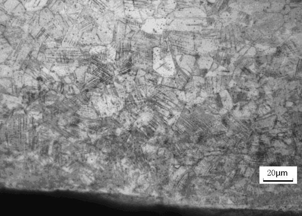
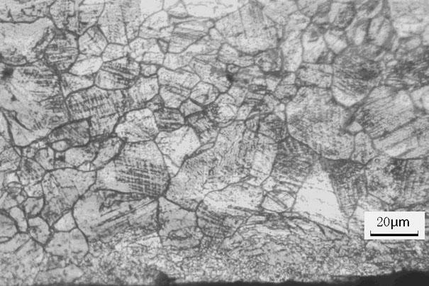
[0022] The metallographic structure of the inner wall of the steel pipe after shot peening is as follows figure 1 As shown, there are many slip bands and dislocation structures. After heat treatment in a heat treatment furnace up to 675°C, heat preservation for 10 hours, and air cooling, the metallographic phase of the inner wall of the steel pipe is as follows: figure 2 It can be seen from the figure that the austenitic shot-peened stainless steel tube still retains the slip band and dislocation structure. The metallographic structure map is obtained by taking a metallographic microscope, and the instrument model is Zeiss Axio observer.D1m.

Embodiment 2

[0024] The alloy composition used in this embodiment is shown in Table 2.

[0025] Table 2: Composition (Wt%) of austenitic stainless steel in Example 2.

[0026] C Si mn P S Ni 0.08 0.20 0.85 0.024 0.005 8.44 Cr Cu Nb N B Al 18.52 2.91 0.53 0.11 0.004 0.010

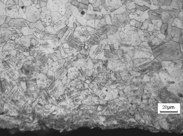
[0027] The metallographic structure of the inner wall of the steel pipe after shot peening is as follows image 3 As shown, there are many slip bands and dislocation structures. After heating up to 700°C in a heat treatment furnace, holding the heat for 2 hours, and air cooling, the metallographic phase of the inner wall of the steel pipe is as follows: Figure 4 It can be seen from the figure that the austenitic shot-peened stainless steel tube still retains the slip band and dislocation structure. The metallographic structure map is obtained by taking a metallographic microscope, and the instrument model is Zeiss Axio observer.D1m.


PUM


Abstract

The invention discloses a heat treatment technology used after austenite shot-blast steel pipe cold deformation. The austenite shot-blast steel pipe comprises chemical components of, by weight: 0.07-0.13% of C, no more than 0.30% of Si, no more than 1.00% of Mn, no more than 0.040% of P, no more than 0.010% of S, 7.5-10.5% of Ni, 17.0-19.0% of Cr, 2.5-3.5% of Cu, 0.30-0.60% of Nb, 0.05-0.12% of N, 0.001-0.010% of B, 0.003-0.030% of Al, and balance of Fe. The technology is characterized in that the heat treatment technology comprises steps that: the austenite shot-blast steel pipe is subject to a heat treatment under a temperature of 650-750 DEG C in a heat treatment furnace for 0.5-10h; the steel pipe is fetched from the furnace, and is cooled. The cooling mode is air cooling. According to the invention, with the heat treatment technology after the austenite shot-blast steel pipe cold deformation, microstructures such as slip bands and dislocations caused by shot-blasting are maintained on the inner surface of the austenite shot-blast steel pipe during a manufacturing process, such that the safety during boiler material application is improved, and a vacancy in a related domestic field is filled up.

Description

technical field [0001] The invention relates to a heat treatment process for a power plant boiler steel pipe, in particular to a heat treatment process for an austenitic shot-peened steel pipe after cold deformation. Background technique [0002] At present, the boiler industry has begun to use austenitic inner wall shot peened steel pipes to improve the performance of boiler pipes against steam oxidation. [0003] In the initial stage of boiler operation, the chromium atoms on the metal surface of the inner wall of the steel pipe are preferentially combined with the oxygen in the steam than the iron atoms to form Cr 2 o 3 film. form Cr 2 o 3 After the thin film is formed, it can slow down the oxidation rate of the substrate on the steam side of the boiler steel pipe. in Cr 2 o 3 In the process of film formation and growth, chromium will continue to be consumed, resulting in a lack of chromium in the metal surface area of ​​the inner wall. In order to replenish the c...

Claims


Application Information

Patent Timeline
Patent Type & Authority Applications(China)
IPC IPC(8): C21D8/10C22C38/54
Inventor 王建泳金用强张波
Owner SHANGHAI BOILER WORKS
Why Eureka
Try Eureka