
Upper air anti-collision guardrail module transfer hanging bracket and construction method

An anti-collision guardrail and shifting formwork technology, applied in the erection/assembly of bridges, bridges, buildings, etc., can solve the problems of slow construction progress, and achieve the effects of short construction period, high quality, and convenient dismantling and assembly.

Inactive Publication Date: 2012-06-13
THE THIRD CONSTR CO LTD OF CHINA CONSTR THIRD ENG BUREAU
View PDF6 Cites 25 Cited by
  • Summary
  • Abstract
  • Description
  • Claims
  • Application Information

AI Technical Summary

Problems solved by technology

The patent mentioned the problem of insecure construction in the past in the background technology, but the patent only provides a 360° rotating workbench to hook the formwork to the formwork with the hook, and the manual operation of the hoist to control the formwork height is convenient for workers to install and operate. The working face still adopts the previous unsafe structure when workers operate, and no technical solution has been given
In addition, only one steel formwork can be disassembled and assembled at a time using the above-mentioned technology, and the progress of the project is slow.

Method used


Image

  • Upper air anti-collision guardrail module transfer hanging bracket and construction method
  • Upper air anti-collision guardrail module transfer hanging bracket and construction method
  • Upper air anti-collision guardrail module transfer hanging bracket and construction method

Examples


Embodiment Construction

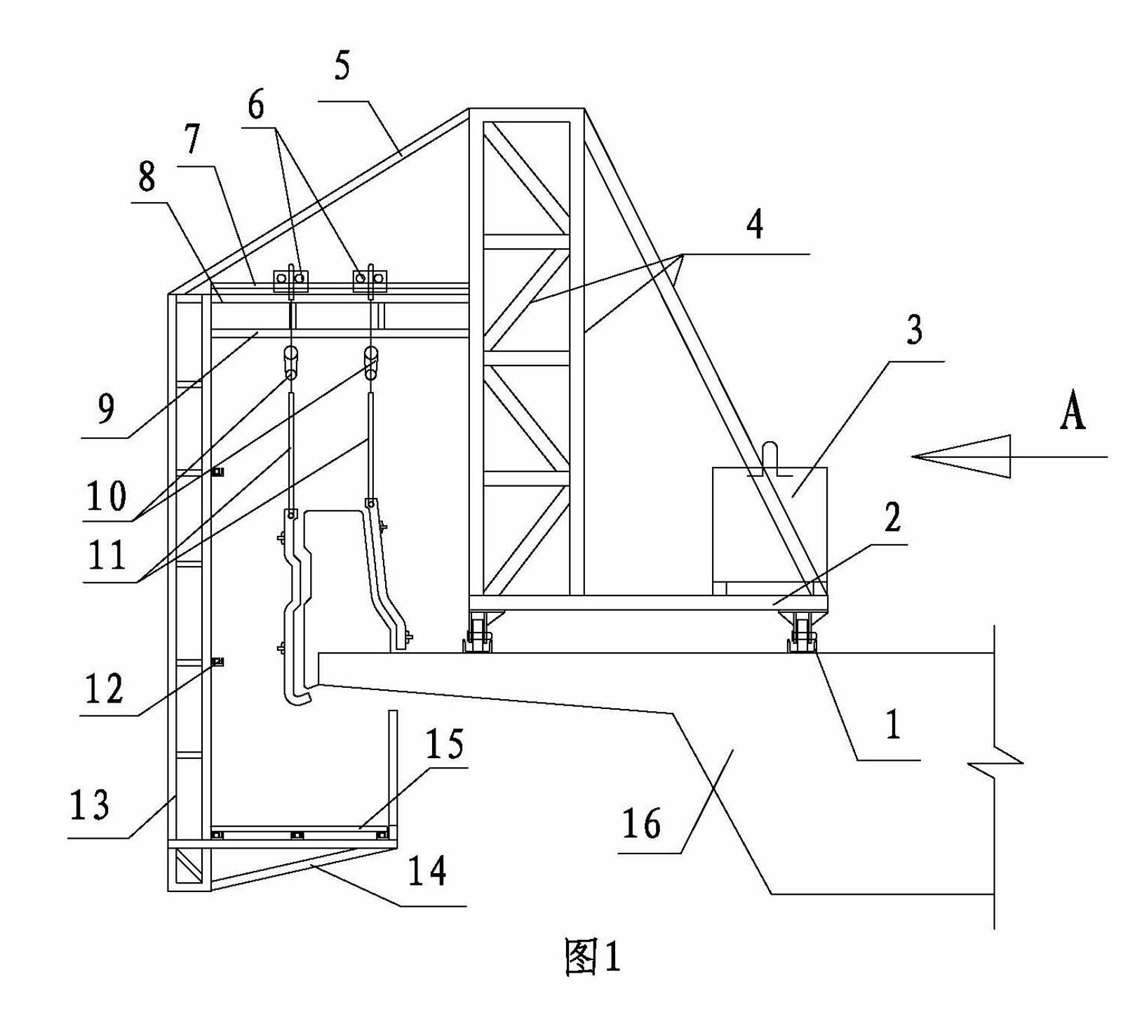
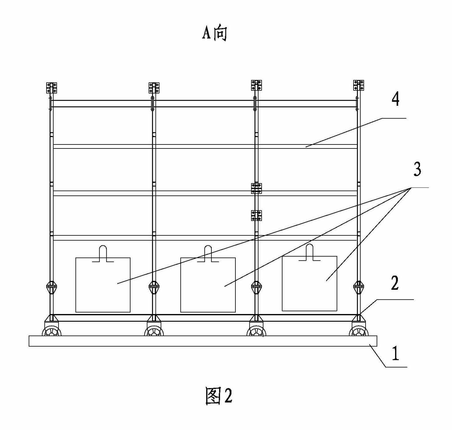
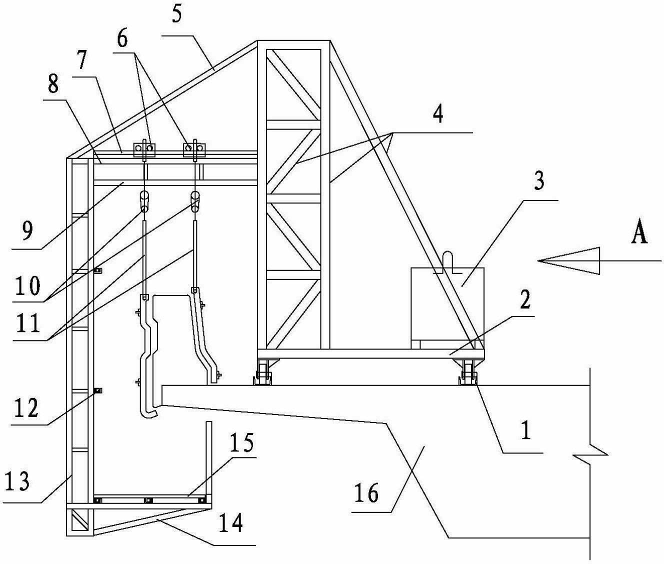
[0022] Such as figure 1 , figure 2 As shown, the high-altitude anti-collision guardrail formwork hanger of the present invention includes two slide rails 1 above the viaduct 16, a trolley 2 is provided on the slide rail 1, and a counterweight 3 and an inner truss 4 are provided on the trolley 2. There are several inner trusses 4 on the trolley 2 of the high-altitude anti-collision guardrail mold transfer hanger of the present invention. The tops of several inner trusses 4 are longitudinally connected by connecting rods 17 . The upper part of each inner truss 4 is connected to the outer truss 13 through the inclined beam 5 , the upper beam 8 and the lower beam 9 . A protective fence 12 is provided on the outer truss 13 . The lower part of the outer truss 13 is connected with a horizontal frame 14, and several horizontal frames 14 are longitudinally connected by pedals 15 to form a workbench. A slideway 7 is provided on the upper beam 8 . Two sliding bodies 6 are slidably ...


PUM


Abstract

Provided are an upper air anti-collision guardrail module transfer hanging bracket and a construction method. The module transfer hanging bracket comprises a sliding rail on a viaduct bridge and a walking car provided with a plurality of counter weights and inner trusses. The plurality of inner girders are longitudinally connected through connecting rods, and each inner girder is connected with an outer girder with a guard railing through an oblique beam, an upper beam and a lower beam. The outer girder is suspended outside a bridge floor, the lower portion of the outer girder is connected with a horizontal frame, and a slide on the upper beam is slidingly connected two slide bodies connected with electric blocks and steel moulding plate hooks. The plurality of outer girders and horizontal frames are connected through footboards to form an anti-collision guardrail module transfer hanging basket which can enable ten (or more than ten) persons to conduct steel moulding plate concrete pouring operation simultaneously, and movement of a steel moulding plate saves time and is convenient and short in time. An operating platform is reasonable in structure, firm and stable, and workers are safe in working high above the ground. The upper air anti-collision guardrail module transfer hanging bracket is connected through bolts, is convenient in assembly and capable of using in a turnover mode, needs to occupy no roads by adopting the upper air anti-collision guardrail module transfer hanging bracket and the construction method, does not influence passing of vehicles under bridges, and has obvious economic benefits.

Description

technical field [0001] The invention relates to a construction method for an anti-collision guardrail of a viaduct, in particular to a mold-moving hanger and a construction method for a high-altitude anti-collision guardrail of a viaduct. Background technique [0002] The traditional method used in the construction of the anti-collision barriers on both sides of the viaduct is to set up double-row scaffolding operating platforms under the viaduct, but in the construction of urban viaducts, due to the impact of heavy traffic flow, there is no condition to erect double-row scaffolding. [0003] Chinese Patent No. 201020217577.5 discloses a "Mobile Rotary Crane for Bridges with Hanging Eaves Cast-in-place Concrete Anti-collision Guardrails", which provides a hanger connected with a workbench through a rotating shaft on a traveling vehicle, and the working The back end of the table is equipped with hoist and counterweight technology. In this technology, the manual rotation hang...

Claims


Application Information

Patent Timeline
IPC IPC(8): E01D21/00
Inventor 何穆刘晓青唐静李玲马新霞邱龙安齐平洲许俊平王小芳何小村
Owner THE THIRD CONSTR CO LTD OF CHINA CONSTR THIRD ENG BUREAU
Learn More