Magneto-rheological damper capable of performing self speed monitoring

A magnetorheological damper, self-monitoring technology, applied in vibration suppression adjustment, non-rotation vibration suppression, etc., can solve problems such as increasing system cost, reducing system reliability, and large installation space

Inactive Publication Date: 2012-06-13
HARBIN INST OF TECH
View PDF4 Cites 0 Cited by
  • Summary
  • Abstract
  • Description
  • Claims
  • Application Information

AI Technical Summary

Problems solved by technology

[0004] The purpose of the present invention is to solve the need for additional dynamic response sensors to realize closed-loop feedback control in the semi-active control of existing magneto-rheological dampers, and the introduc...

Method used


Image

  • Magneto-rheological damper capable of performing self speed monitoring
  • Magneto-rheological damper capable of performing self speed monitoring
  • Magneto-rheological damper capable of performing self speed monitoring

Examples


specific Embodiment approach 1

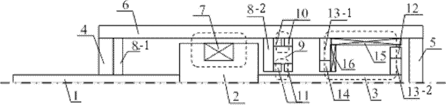
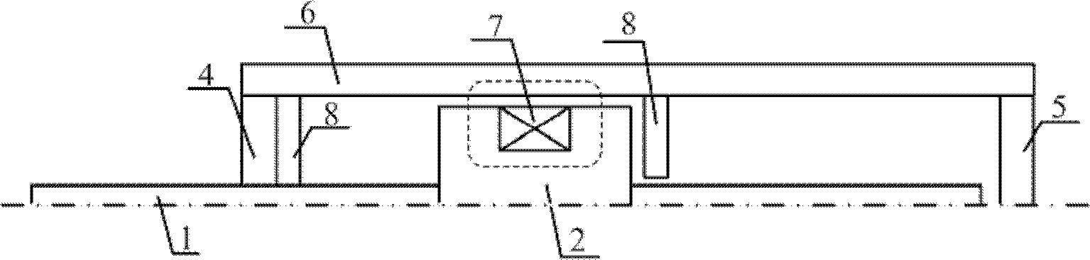
[0008] Specific implementation mode one: combine figure 1 Describe this embodiment, a magneto-rheological damper capable of self-monitoring speed described in this embodiment includes an outer piston rod 1, a piston core 2, an inner piston rod 3, a left end cover 4, a right end cover 5, a cylinder body 6, Exciting coil 7, No. 1 plastic sealing body 8-1 and No. 2 plastic sealing body 8-2, cylinder body 6 is a cylindrical body, right end cover 5 is fixed on the right end of cylinder body 6, left end cover 4 is fixed on the bottom of cylinder body 6 The left end, the center of the left end cover 4 has a through hole, the center of the No. 1 plastic sealing body 8-1 has a through hole, the No. 1 plastic sealing body 8-1 is located in the cylinder body 6, and the No. 1 plastic sealing body 8-1 1 is in close contact with the inner wall of the left end cover 4 and the cylinder body 6, the center of the second plastic sealing body 8-2 has a through hole, the second plastic sealing bo...

specific Embodiment approach 2

[0013] Specific implementation mode two: combination figure 1 Describe this embodiment, the difference between this embodiment and Embodiment 1 is that it also includes a compensation coil 16, the compensation coil 16 is circular, and the compensation coil 16 is fixed on the magnetically permeable steel part 13-1 of the No. 1 sensing magnetic circuit right end face. Other components and connections are the same as those in Embodiment 1.

[0014] As the piston rod is pulled outward, the magnetic flux leakage inside the sensing magnetic circuit will affect the sensing accuracy. For this reason, a compensation coil 16 is added inside the damper in the present invention to monitor the change of the magnetic flux leakage. The voltage of the compensation coil is proportional to The product of coil turns and leakage flux, the compensation voltage is:

[0015]

[0016] Among them, N is the number of coil turns, V is the coil voltage;

[0017] Adding the above compensation volta...


PUM


Abstract

A magneto-rheological damper capable of performing self speed monitoring relates to the damping control technology and aims at solving the problem that an existing magneto-rheological damper is short of a self compensating function and has a self speed sensing function in magneto-rheological control. Assemblies for measuring self speed are increased in a tail portion cylinder body of the existingmagneto-rheological damper and includes a magnetic steel part, two first permanent magnets, two second permanent magnets, a first permanent magnet for sensing a magnetic circuit, a first magnetic steel part for sensing a magnetic circuit, a second magnetic steel part for sensing a magnetic circuit, a second permanent magnet for sensing a magnetic circuit and a sensing coil. With the motion of an inner piston rod, the first permanent magnet for sensing the magnetic circuit is fixed at the end of the piston rod, number of turns of the coil excited by a magnetic field is decreased or increased in a direct proportion mode along with the left-right motion of the inner piston rod, accordingly change of magnetic linkage of the sensing coil is proportional to displacement of the piston, and piston speed can be obtained according to the change of sensing voltage in the coil. The magneto-rheological damper capable of performing the self speed monitoring is used for the damping control technology.

Description

technical field [0001] The present invention relates to damping control technology. Background technique [0002] The magnetorheological damper is a new type of damping device that utilizes the rheological effect of magnetorheological fluid under the action of a magnetic field to adjust the damping force. It has the advantages of rapid, continuous, and adjustable damping force, and can realize structural vibration. intelligent control. [0003] The traditional semi-active control of magnetorheological dampers requires additional dynamic response sensors to realize closed-loop feedback control. The introduction of additional sensors will make the system more complex, require a larger installation space, increase system cost and reduce system reliability. Contents of the invention [0004] The purpose of the present invention is to solve the need for additional dynamic response sensors to realize closed-loop feedback control in the semi-active control of existing magneto-r...

Claims


Application Information

Patent Timeline
IPC IPC(8): F16F9/53
Inventor 关新春郭鹏飞李惠欧进萍
Owner HARBIN INST OF TECH
Why Eureka
Try Eureka