Magneto-rheological damper capable of performing self speed monitoring
A magnetorheological damper, self-monitoring technology, applied in vibration suppression adjustment, non-rotational vibration suppression, etc., can solve the problems of system complexity, reduce system reliability, and increase system cost, etc.
- Summary
- Abstract
- Description
- Claims
- Application Information
AI Technical Summary
Problems solved by technology
Method used
Image
Examples
specific Embodiment approach 1
[0008] Specific implementation mode one: combine figure 1 Describe this embodiment, a magneto-rheological damper capable of self-monitoring speed described in this embodiment includes an outer piston rod 1, a piston core 2, an inner piston rod 3, a left end cover 4, a right end cover 5, a cylinder body 6, Exciting coil 7, No. 1 plastic sealing body 8-1 and No. 2 plastic sealing body 8-2, cylinder body 6 is a cylindrical body, right end cover 5 is fixed on the right end of cylinder body 6, left end cover 4 is fixed on the bottom of cylinder body 6 The left end, the center of the left end cover 4 has a through hole, the center of the No. 1 plastic sealing body 8-1 has a through hole, the No. 1 plastic sealing body 8-1 is located in the cylinder body 6, and the No. 1 plastic sealing body 8-1 1 is in close contact with the inner wall of the left end cover 4 and the cylinder body 6, the center of the second plastic sealing body 8-2 has a through hole, the second plastic sealing bo...
specific Embodiment approach 2
[0013] Specific implementation mode two: combination figure 1 Describe this embodiment, the difference between this embodiment and Embodiment 1 is that it also includes a compensation coil 16, the compensation coil 16 is circular, and the compensation coil 16 is fixed on the magnetically permeable steel part 13-1 of the No. 1 sensing magnetic circuit right end face. Other components and connections are the same as those in Embodiment 1.
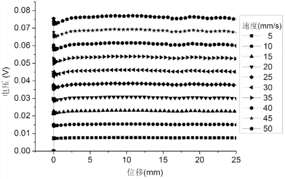
[0014] As the piston rod is pulled outward, the magnetic flux leakage inside the sensing magnetic circuit will affect the sensing accuracy. For this reason, a compensation coil 16 is added inside the damper in the present invention to monitor the change of the magnetic flux leakage. The voltage of the compensation coil is proportional to The product of coil turns and leakage flux, the compensation voltage is:
[0015]
[0016] Among them, N is the number of coil turns, V is the coil voltage;
[0017] Adding the above compensation volta...
PUM
 Abstract
Description
Claims
Application Information
 - R&D
- Intellectual Property
- Life Sciences
- Materials
- Tech Scout
- Unparalleled Data Quality
- Higher Quality Content
- 60% Fewer Hallucinations
Browse by: Latest US Patents, China's latest patents, Technical Efficacy Thesaurus, Application Domain, Technology Topic, Popular Technical Reports.
© 2025 PatSnap. All rights reserved.Legal|Privacy policy|Modern Slavery Act Transparency Statement|Sitemap|About US| Contact US: help@patsnap.com


