Passive temperature sensor and test system based on same

A technology of temperature sensor and sensor, which is applied to thermometers, thermometers with directly heat-sensitive electric/magnetic elements, instruments, etc., can solve problems such as line aging, limit the application of sensors and sensor systems, and system failure, and achieve accuracy improvement , to achieve the effect of passive

Active Publication Date: 2012-06-13
HANGZHOU INNOVATION RES INST OF BEIJING UNIV OF AERONAUTICS & ASTRONAUTICS +1
View PDF3 Cites 6 Cited by
  • Summary
  • Abstract
  • Description
  • Claims
  • Application Information

AI Technical Summary

Problems solved by technology

In this way, the application of sensors and sensor systems is limited in places where wiring is not suitable or where personnel cannot reach.
In addition, if the sensor system has not been used for a long time after installation, the aging of the circuit will cause the system to fail
If a dry battery is used for power supply, there will also be a problem that the battery energy will be exhausted due to excessive use time, and the power supply for the normal operation of the sensor system will not be able to cause the system to fail.

Method used


Image

  • Passive temperature sensor and test system based on same
  • Passive temperature sensor and test system based on same
  • Passive temperature sensor and test system based on same

Examples


Embodiment Construction

[0025] The specific embodiments of the present invention will be described below in conjunction with the accompanying drawings in order to better understand the present invention. It should be particularly reminded that in the following description, when detailed descriptions of known functions and designs may dilute the main content of the present invention, these descriptions will be omitted here.

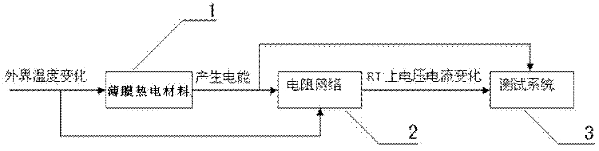
[0026] figure 1 Shown is a block diagram of a passive temperature sensor system. When the outside temperature changes, the thermoelectric material converts the change in the temperature field into electrical energy. The electrical energy generated will power the resistive voltage divider network and subsequent equipment. The back-end measurement circuit measures the resistance of the thermistor to obtain the current The temperature value.

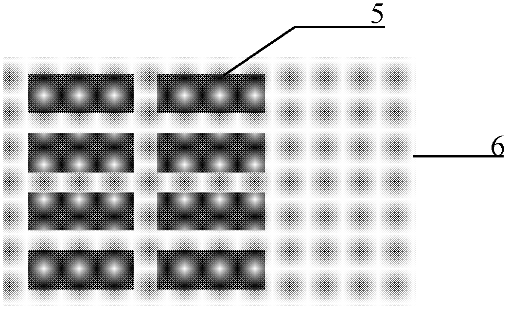
[0027] figure 2 Shown is the top view of the upper electrode plate of the passive temperature sensor. The electrode plate uses a 4cm*5cm (length...


PUM


Abstract

The invention provides a passive temperature sensor and a test system based on the same. The passive temperature sensor comprises a lamellar directional thin-film thermoelectric material Bi0.5Te1.5Se3 (4) composed of a nano-wire array, a Ti barrier layer (11), a Cu electrode (5), a Ni adhesion layer (10), an AlN substrate pole plate (6), a voltage-division type resistor temperature-measuring network and a diode (9), wherein the voltage-division type resistor temperature-measuring network is composed of a high-precision standard resistor (7) and a thermistor (8) which are connected with each other in series; the barrier layer (11) is used for preventing a diffusing effect between an electrode and a thermoelectric material; the adhesion layer (10) is used for connecting a metal electrode and a semiconductor substrate; the standard resistor (7) and the thermistor (8) are used for measuring the temperature; and the diode (9) is used for preventing current from entering into the thermoelectric material in an active work mode. According to the invention, electric signals generated by triggering the passive temperature sensor are used as a detection signal and a power supply, so that thepower is not needed to be supplied to the sensor.

Description

Technical field [0001] The invention relates to the field of pyroelectric sensors, in particular to a passive temperature sensor and a test system based on passive temperature sensor components. Background technique [0002] At present, most logarithmic sensors require power supply, and all sensor systems have external power supplies or internal batteries. In this way, the application of sensors and sensor systems is limited in places that are not suitable for wiring or people cannot reach. In addition, if the sensor system is not used for too long after installation, the aging of the circuit will cause the system to fail. If a dry battery is used for power supply, there will also be a problem that the battery energy is exhausted due to excessive use time, and the sensor system cannot be supplied with power for normal operation, resulting in system failure. Therefore, a key constraint on the effectiveness of the sensor system is the power supply of the system. Summary of the i...

Claims


Application Information

Patent Timeline
Patent Type & Authority Applications(China)
IPC IPC(8): G01K7/22
Inventor 邓元史永明祝薇王瑶叶慧红
Owner HANGZHOU INNOVATION RES INST OF BEIJING UNIV OF AERONAUTICS & ASTRONAUTICS
Why Eureka
Try Eureka