
Drainage method for high-fall heavy-caliber oil-gas pipeline after pressure testing
An oil and gas pipeline, large-diameter technology, applied in the application of stable tension/pressure to test the strength of materials, by measuring the acceleration and deceleration rates of fluids, and using liquid/vacuum for liquid tightness measurement, etc. It can solve problems such as pipeline bursting , to achieve the effect of convenient operation, clear principle and simple structure
- Summary
- Abstract
- Description
- Claims
- Application Information
AI Technical Summary
Problems solved by technology
Method used
Image

Examples
Embodiment Construction
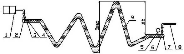
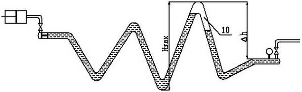
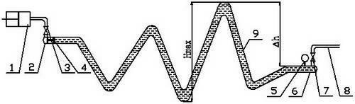
[0027] according to figure 1 As shown, the pipeline is laid in a high drop area, assuming that the maximum elevation difference in the pipeline is H max 100m, pipe outer diameter D It is 1219mm, the wall thickness is 18.4mm, and the construction site temperature is 20°C. Before the pressure test on the main line 9, install a pressure gauge 5 on the pressure test head A6 at the drain end, weld a branch pipe on the pressure test head A6 and install a high pressure gate valve A7, and install a drain on the outlet end of the high pressure gate valve A7. Pipe 8, and then weld a branch pipe to the pressure test head B2 at the other end of the main line 9 and install the high pressure gate valve B3. After the pressure test is completed, the high pressure gate valve A7 and the high pressure gate valve B3 are in a closed state.
[0028] Choose the air compressor 1 with appropriate displacement and rated discharge pressure, and the rated pressure of air compressor 1 P not lower than ,amon...
PUM
 Abstract
Description
Claims
Application Information